June 2024 I Volume 45, Issue 2
Digital Test and Evaluation: Validation of System Models as a Key Enabler
June 2024
Volume 45 I Issue 2
IN THIS JOURNAL:
- Issue at a Glance
- Chairman’s Message
Conversations with Experts
- A T&E Career of Learning by Doing: A Conversation with Mr. Edward R Greer
- A Bourbon with Rusty: A Conversation with Russell L. Roberts
Values in T&E
- My T&E Career, The First 25 Years
- The Architecture Analogy in Test Planning: An example of the T&E value of 'Well-Planned'
- Values in Operational Testing
Technical Articles
- Digital Test and Evaluation: Validation of System Models as a Key Enabler
- Statistical Review of the Cyber Test Process
- The Robust Classical MTBF Test
Workforce of the Future
- Deep Learning for Autonomous Vehicles
- The K-D Tree as an Acceleration Structure in Dynamic, Three-Dimensional Ionospheric Modeling
- Optimization Engine to Enable Edge Deployment of Deep Learning Models
News
- Association News
- Chapter News
- Corporate Member News
![]()
Digital Test and Evaluation: Validation of System Models as a Key Enabler
James R. Winton, Captain, M.S.
United States Air Force
Wright-Patterson Air Force Base, OH
![]()
![]()

John M. Colombi, Ph.D.
Air Force Institute of Technology (AFIT)
Wright-Patterson Air Force Base, OH
![]()
![]()
Abstract
The Department of Defense (DoD) is undergoing a Digital Transformation (DT), which will affect all acquisition processes in some way. As documents are replaced with digital models, the existing processes will be required to facilitate emerging concepts like the Rapid Acquisition Process (RAP) and Test and Evaluation as a Continuum (TEaaC). Traditional Test and Evaluation (T&E) will be augmented by automated digital testing in all program lifecycle phases. Digital testing will rely on many forms of digital models, including Model-Based Systems Engineering (MBSE), linked together via a digital thread and an Authoritative Source of Truth (ASOT). Validation of such digital artifacts will be paramount in assuring system developers and test engineers use accurate and credible models for decisions. This paper proposes a model-based validation technique, details a proof-of-concept, and describes how it may enable future acquisition.
Keywords: Model-based Systems Engineering, Model Requirements, Digital System Models, Validation, Rapid Acquisition, Test and Evaluation
Introduction
A Digital Transformation (DT) is underway in the U.S. Department of Defense (DoD). The transition from static, document-based products to model-based artifacts will permeate the entire acquisition enterprise. All aspects of the product lifecycle, from development to test to operations, sustainment, and disposal, should leverage interconnected models that contribute to and pull from digital artifacts. The future of acquisition is digital; however, the transformation will take time, effort, funding, and workforce adoption to be successful. Many of the implemented processes are being created at the program or project level, with several organizations attempting to codify and share best practices.
Such digital efforts have been instituted across the U.S. Air Force (USAF) in various programs and at different stages of the product life cycle. Many of the implemented processes are being created at the program or project level, with several organizations attempting to codify and share best practices. Recently, the Ground-Based Strategic Deterrent (GBSD) performed a comprehensive trade space study by evaluating over one million system configurations to inform the selection of the optimal solution. The next-generation jet trainer, the T-7 Redhawk, was a pioneer program that integrated digital practices and modeling from the program origin in the pre-Milestone-A phase. Additionally, existing born-analog programs for aircraft like the A-10, the B-52, and the F-16 have leveraged varying degrees of digital practices where the return on investment (ROI) supported the dedication of resources. In a 2021 study, researchers determined that the Submarine Warfare Federated Tactical Systems (SWFTS) was able to save the U.S. Navy a conservative $10M by investing in a model-based requirements process that generated a 3.26 ROI of the initial $3.2M MBSE investment (Rogers and Mitchell 2021).
Successful applications have resulted in increased support for the DT initiative from department leadership and acceptance by the workforce engaged in all six DoD Adaptive Acquisition Framework pathways. One area that requires major programs to commit significant amounts of funding and schedule is Test and Evaluation (T&E). For decades, T&E has occurred near the end of the development cycle, just before manufacturing, operations, and sustainment. When errors or problems are eventually identified by test teams, the solutions are costly in terms of both funding and schedule. Similar to the concepts of agile software development, the new digital acquisition enterprise should incorporate T&E early and often in the system life cycle to realize the benefits of early issue identification.
As programs implement digital model management, there will be a proliferation of system models that are used to inform decisions. This paper posits that early validation of such models can aid in cost and schedule reductions by supplying such models to the T&E community early in the development process.
Background and Related Work
The traditional DoD acquisition process has been characterized as slow, rigid, and costly. The Major Capability Lifecycle, shown in Figure 1, contains five phases, three major milestones, and many decision points and reviews. Each has been executed in the past with document-based views of the system at a given point in time (AcqNotes 2021). A weakness of the traditional, linear, major capability acquisition method is that a large amount of data used in development activities and decisions is communicated and stored separately in disjointed and static forms across organizations, tools, and environments (Zimmerman, Gilbert, and Salvatore 2019).
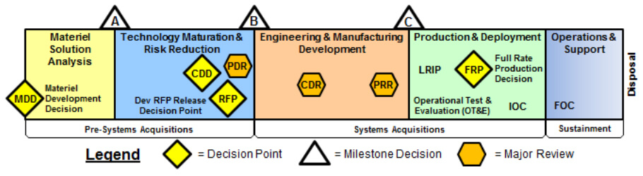
Figure 1. Major Capability Lifecycle (AcqNotes 2021)
Recognizing the limitations of the one-size-fits-all approach, the DoD defined several paths for system development, including urgent or rapid acquisition and agile software systems, in addition to traditional major capabilities (OUSD(A&S) 2021). The Rapid Acquisition Process (RAP) is leveraged by the Unified Combatant Commands to build, integrate, test, and deploy systems to overcome changing adversary threats and apply force against near-peers (Goldwasser and Ryder 2019). The field is driven by a rapid development methodology that uses technical expertise, analysis techniques, models, simulations, and tools in an agile process to support program managers in resource-constrained environments. A key element of RAP is the application of systems engineering (SE) to greatly enhance communication and increase understanding of the complex DoD systems under development (Goldwasser and Ryder 2019).
The new acquisition model fundamentally changes the approach of discrete and separate development phases into a continuous engineering and deployment construct (Guertin and Hunt 2017). The traditional Design-Build-Test methodology will be replaced by a Model-Analyze-Build approach (ODASD(SE) 2018). The resulting product is increments of capability delivered to the warfighter that must be affordably tested and fielded in short time frames (Guertin and Hunt 2017). Affordable testing is crucial to successful agile processes.
However, testing of increasingly complex DoD systems presents other challenges. Issues like long execution timelines, ambiguous test procedures, and unstandardized documentation reveal the opportunity for innovation and optimization within the T&E domain (Walker 2020). Implementation of automated testing can decrease test time and reduce uncertainty (Bjorkman, Sarkani, and Mazzuchi 2013). MBSE techniques facilitate complex system design and documentation processes that eliminate some of the burdens of document-based processes (Topper and Horner 2013). Additionally, MBSE provides authoritative artifacts that are standardized to support regressions, formalize the organization of testing and test plans, and tie actions and results to requirements (Walker 2020).
In support of RAP, and championed by the U.S. Navy, the services are leveraging a Capabilities-Based Test and Evaluation (CBTE) methodology to evaluate and verify system capabilities (Goldwasser and Ryder 2019). T&E leaders have integrated it into a new approach coined “Test and Evaluation as a Continuum” (TEaaC). The method transitions T&E from serial activities to an integrative framework focused on a continuum of activities with the following three key attributes (Collins and Senechal 2023):
1.Capability and outcome-focused testing,
2.Agile, scalable evaluation framework; and,
3.Enhanced test design
The following research provides a foundational unit for the future of digital T&E. The digital transformation will leverage models and digital artifacts contained in the Authoritative Source of Truth (ASOT). Before acceptance into the ASOT, a digital model must be verified and validated for a particular use (OUSD(R&E) 2022). Validation of an MBSE model, a basic component of an overall system model, presents a challenge not seen in traditional systems because traditional systems have a real-world instantiation, or referent data, while a system model representing requirements, structure, and behavior may not. This requires three new modeling elements: a validation use case, a model requirement, and a validation test case (Winton et al. 2023). By creating a digital system model with the three validation components in mind, it can be used in the capabilities-based, continuum of testing to deliver incremental capabilities to the customer.
Enabling Rapid Acquisition with Digital T&E
A key enabler of rapid acquisition will be rapid, digital T&E. As the DoD designs, builds, and fields increasingly complex systems, modeling and simulation (M&S) is often the safest, most cost-effective, and sometimes the only means available to test systems (Jones and Adams 2022). General John Hyten, a Vice Chairman of the Joint Chiefs of Staff, states that a top priority is to re-inject speed into both the requirements and acquisition process to drive more lethal, resilient, and rapidly adaptable military forces (Brewer and Magness 2020). Models, and the associated indefinite set of viewpoints that comprise them, are quickly becoming the new medium for transferring system knowledge and understanding from the stakeholders to the developers (Goldwasser and Ryder 2019). In pursuit of speed, programs in the digital environment will use models to evaluate requirements satisfaction before expending time and resources to create a physical system (Jones and Adams 2022).
As system models are leveraged for T&E efforts via M&S, the subsystem, and component-level models will require validation before the execution of a full-system test. In the new era of Digital Engineering (DE), instances will arise for which models do not exist, are not validated for the intended use, or are not validated to the required fidelity or authority (Jones and Adams 2022). Therefore, before the acceptance of the component-level and subsystem models, the program must ensure that the “model is built right” and that the “right model was built.” Validation is usually performed by comparing the output of M&S to a real-world source of referent data which ensures the information produced by the model aligns, within certain bounding conditions, with the real world (Elele, Hall, and Turner 2022). The credibility of M&S models can be defined in terms of capability, accuracy, and usability (Elele, Hall, and Turner 2022). Each of the three terms of credibility can be defined by, and executed in, a model use case test.
In instances where there is no existing referent data, a new validation method must be applied. As described in the following sections, the proposed method relies on a unique modeling convention and element called a validation use case. The validation use case, similar to a use case that a user executes during Operational Test and Evaluation (OT&E), defines how the model will be used, what capabilities the model is required to have, and a bounding condition for which the model output is accurate.
A Validation Framework and Process
Early incorporation of T&E can assist the SE process and provide early indications that requirements and architectures are feasible, testable, verifiable, and possible to validate (Miller 2017). A validation method that implements both model use cases and T&E concepts has the potential to increase the speed of delivery of models in a rapid acquisition environment.MBSE will not succeed without correct and complete SE models (Hecht and Chen 2021). The metamodel, shown in Figure 2, articulates the difference between classic system requirements and the new concept of model requirements. The metamodel provides the framework for model validation. Model requirements are satisfied by the system model, not the system itself, and are validated by specific validation test cases determined by the model use case.
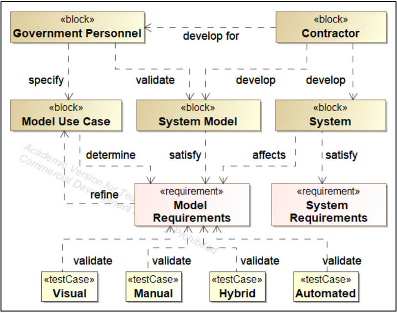 Figure 2. Metamodel for Government Validation of Digital System Models (Winton et al. 2023)
The model validation process contains the three elements described above and is outlined in Figure 3. Definition of the model use case is the critical first step in determining the scope, bounding principles, and implementations of the modeling effort. The model use case dictates the data or information that the final model must produce. Data in the form of parametric output, structural views, or a requirements satisfaction matrix, are three such examples and determine the necessary aspects to be modeled (Winton et al. 2023). The second step is to use a custom Systems Modeling Language (SysML) stereotype titled ‹‹modelRequirement›› to create the model elements that refine the use case. Identification of a method or methods for validation of each model requirement is accomplished in the third step by creating model validation test cases. The validation test case is a custom SysML test case that distinguishes between system and model test cases and completes the first half of the process, from left to right in Figure 3.
The process is completed by tracing back through the validation chain. Manual or automated methods are used to execute the model validation test case and validate the model requirement. The validated requirement, in turn, refines the model use case and produces a validity result.
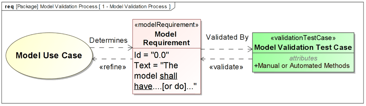 Figure 3. Model Validation Process (Winton et al. 2023)
The concept can be applied to both model-based (“born-digital”) and document-based (“born-analog”) processes. Government acquisition personnel can identify an existing process or system and define possible model use cases such as a design review, fault identification, impact analysis on diminishing manufacturing sources, new supplier maturation, requirements change impacts, cyber vulnerability, and airworthiness. Existing program documentation should be translated into model requirements by asking “What must the model do to meet the defined acquisition use?”
A SysML Validation Profile
A profile defines limited extensions to a reference metamodel to adapt the metamodel to a specific platform or domain (Object Management Group 2009). The framework for model validation extended select elements from the SysML Profile for the Unified Modeling Language. Extensions for the ‹‹requirement››, ‹‹test case››, and ‹‹trace›› stereotypes are shown in Figure 4. Other work in T&E model-based profiles has been recently proposed by Colombi et.al (2023).
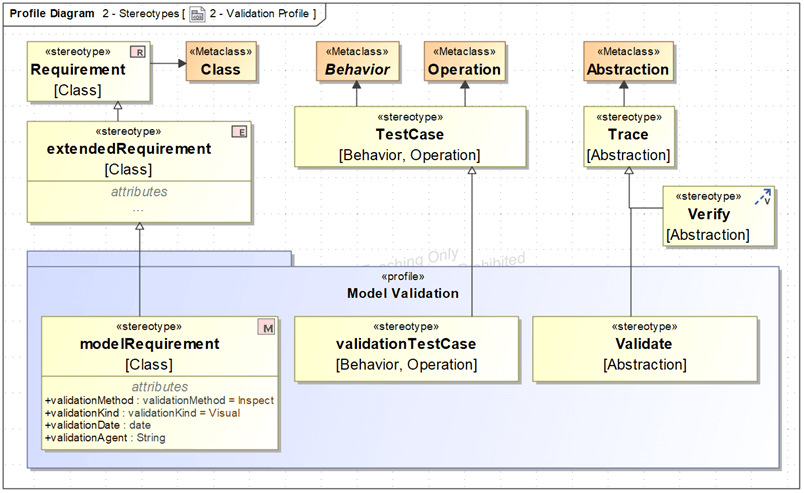 Figure 4. Custom SysML Profile for Model-Based Validation
A ‹‹model requirement›› stereotype is generalized from the ‹‹extended requirement›› stereotype and allows inheritance of attributes like source, risk, and verify method, in addition to the attributes of the parent class requirement. The element also holds unique attributes like validation method, validation kind, validation date, and validation agent which are defined with separate enumeration lists. The attributes allow a full description of the validator, validation methods, and the model location on the spectrum of manual to automated methods.
Relationships like verify are inherent to the SysML language and allow connections of elements and the creation of traceability links between requirements, physical and functional components, activities, and simulation results (Winton et al. 2023). The new profile contains a ‹‹validate›› stereotype which creates a validate relationship, generalized from trace, and distinguishes between classic verification activities and the proposed validation activities.
The modeler can use the model requirements and proposed validation test cases to decide the method by which the validation will occur. Validation methods vary in fidelity, complexity, and the extent of required resources for execution. The validation method enumeration list represents the traditional verification methods which are inspect, analyze, demonstrate, and test (BKCASE Editorial Board 2014). The validation kind defines the level of automation for a validation activity and includes visual, manual, hybrid, and automated enumeration literals.
Application of the Validation Framework to Small UAS
Workshop
The Air Force Institute of Technology (AFIT), Wright-Patterson Air Force Base, Ohio allows students to select a specialization sequence in Small Unmanned Airborne Systems. The three-course track drives students to develop a system over three quarters using the DoD rapid acquisition methodology. The students work with a real-world customer in the first course to elicit requirements, refine a Concept of Operations, perform the design work, and seek approval of a Preliminary Design Review (PDR). The second course requires students to perform design tradeoffs, finalize a system baseline and design, acquire components, and secure approval to proceed in development via a Critical Design Review (CDR). The third course begins with a test planning process and leads to the approval of both a Test Readiness Review (TRR) and a Safety Review Board (SRB). Next, the students execute flight testing to collect data and measure the performance of the prototyped system. The final review of the sequence is a combined System Verification Review (SVR) and Production Readiness Review (PRR) where the students present the results of the RAP.
The structured environment of the sUAS sequence was identified as a logical application area to capture face validity for the validation framework and profile. The validation was workshopped with one of the authors during a project based on the multirotor Tarot 960 Hexframe with Pixhawk 2 Autopilot sUAS. The digital system model was created as an instance of the AFIT SUAS Reference Architecture (RA) which is leveraged to transfer domain knowledge to students, integrate MBSE into the design process, and support the rapid acquisition process.
The first step in workshopping the validation framework to the Tarot Hexframe Multirotor digital system model was the identification of a model use case. Relevant to the sUAS mission of the USAF, a simulated power component upgrade was chosen as the use case for the system-in-sustainment and generalized to “SUAS System Upgrade.” Specifically, from Figure 5 below, the “Perform Sizing Calculations” use case was selected as the use case of interest to determine the acceptability of a battery replacement within the form, fit, and function requirements of the existing aircraft. The use case was then decomposed and translated into model requirements, shown in Figure 6.
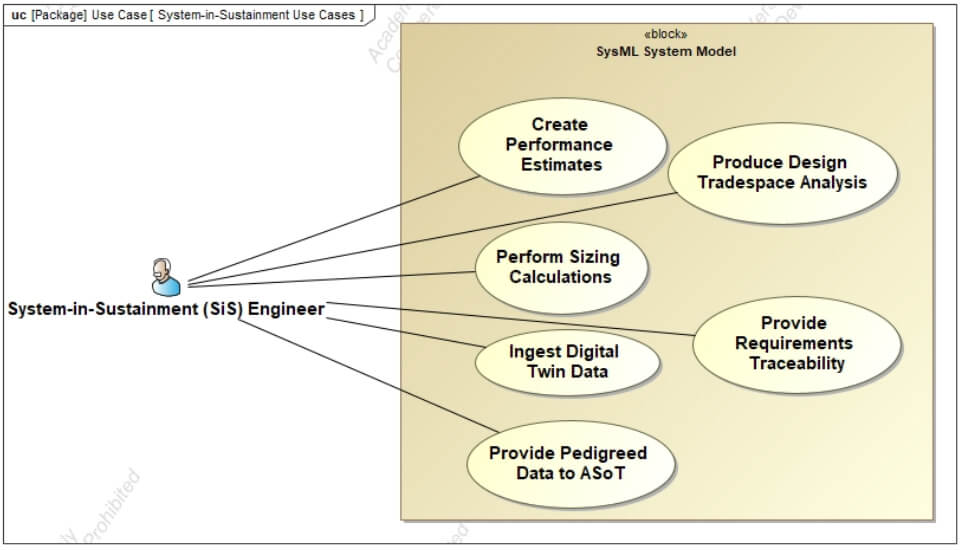 Figure 5. Use Cases for System-in-Sustainment Models
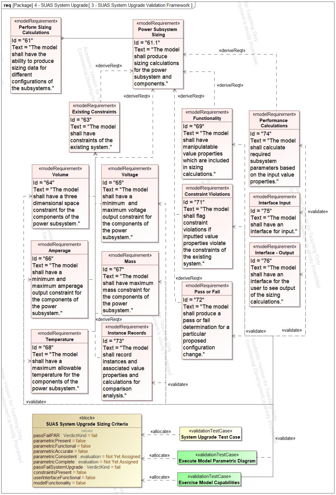 Figure 6. Model Requirements, Validation Test Cases, and Context Block for System Upgrade
The second step defined two validation test cases to validate the overall Power Subsystem Sizing model requirement and the thirteen derived model requirements that spanned model functionality, performance calculations, interfaces, constraints, and value properties. The test cases were modeled as SysML activity diagrams. These are visual process models very representative of a “test card.” These models can produce outputs and pass or fail criteria. The first test case (top of Figure 7) evaluated the functionality, constraints, and interfaces of the model. The second test case (bottom of Figure 7) leveraged a parametric model created within the multirotor digital system model to assess the sizing calculations. The sizing parametric diagram is shown in Figure 8 for a variety of design factors. These can be evaluated against requirements, or eventually compared to actual test data.
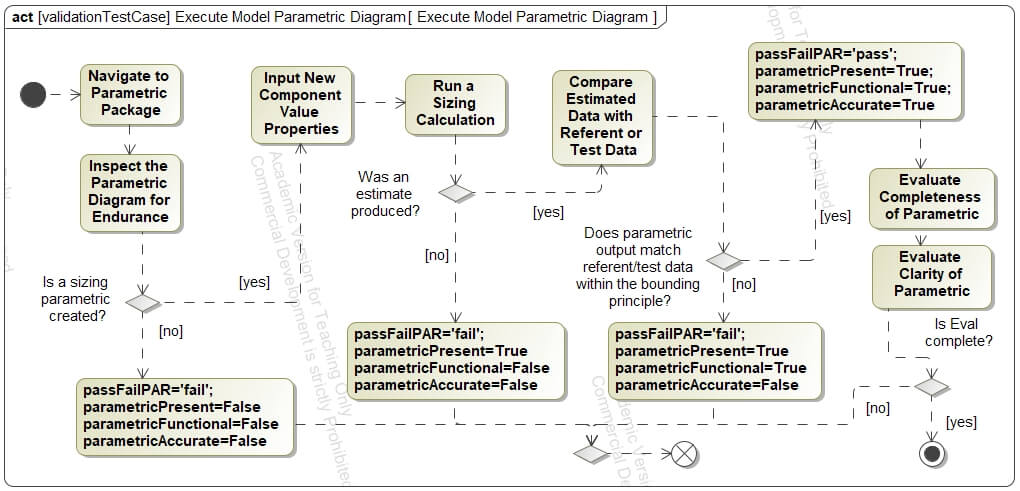
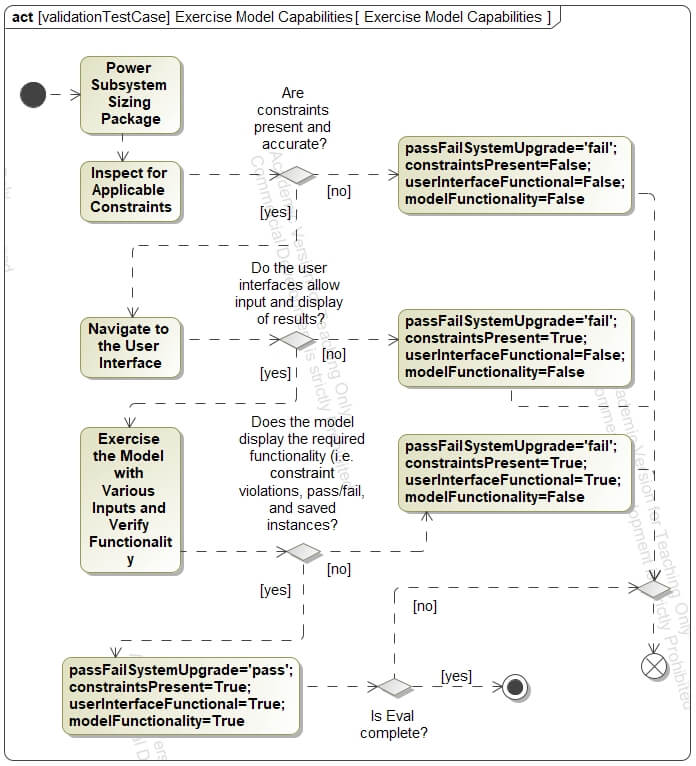 Figure 7. Validation Test Cases Shown in SysML Activity Diagrams
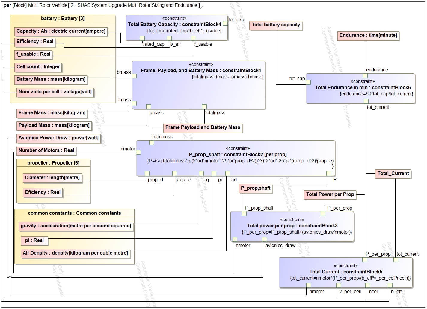 Figure 8. Multirotor Sizing Estimate Parametric Diagram
In the third and final step, a “SUAS System Sizing Criteria Block,” shown in the top right of Figure 8, was created to store the value properties produced by the simulated test cases. The validation test cases were each allocated to the criteria block and simulated “in context.” The logic flows, driven by modeler input, produced value properties that were stored in the block instance. Each simulation of a different battery can create a new instance of the criteria block as a validation scorecard. The validation scorecard contains true or false, pass or fail, and subjective evaluations that pertain to the model requirements.
Output accuracy is the “degree of matching” between the results and the real world. The real world, as defined in M&S, can either be a benchmark against another credible simulation, face validation through subject matter expert review, or results validation through empirical data comparison (Elele, Hall, and Turner 2022). In summary, the output accuracy requirement drives the validation criteria used to determine the validity of the model for the intended use case. The proof-of-concept shows that the model and associated functionality can serve to produce actionable information for a program augmenting live flight tests.
Face Validity – Deployment
Following the workshop and prototyping of the method, the framework was deployed during the next academic year on three digital design projects. Three groups of 4-5 students each began analyzing a concept of operation (CONOPS). The three CONOPS involved: 1) performing visual inspection of buildings, infrastructure and aircraft in support of the Civil Engineering or aircraft maintenance missions, 2) creating and/or updating maps of existing or proposed basing locations using aerial photogrammetry, and 3) performing auto-landing operations in areas where GPS is unavailable.
Professors of the first course updated the original set of system and model requirements for the model-based PDR. This resulted in 13 categories of 46 model requirements. The 13 categories were: Incremental Updates, Use Case Model, Functional Decomposition, Physical Hierarchy, Activity Diagrams, Functional Allocation, Interfaces, Requirements Flow Down, Requirements Fulfillment Analysis, Risk Assessment, Test Strategy, PDR presentation and model delivery, and Project Management.
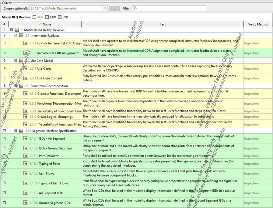
For the next course, ending in a model-based CDR, students were given an additional 29 model requirements in eight categories, as well as having to update all PDR model artifacts. The categories were Incremental Updates, Physical Hierarchy, Test Strategy, CDR deliverables, Project Management, Segment Interface Specification, and Technical Performance Measures (TPMs). An extract is shown in Table 1.
Table 1. Extract Examples of PDR and CDR Model Requirements
Face Validity – Results
Student feedback across all three groups identified the following perceived benefits and challenges:
- Clarity: “Helps knowing exactly what you want and where”; “removes ambiguity.”
- Constraining: “constrained how to provide a PDR deliverable within the tool’s capability”; “sometimes you have to leave CATIA [SE tool] to best perform a PDR task.” Students used MATLAB or python for performance evaluation and google-integrated Gantter for schedules and project management. Efforts are underway to integrate MATLAB and python algorithms with CATIA; Gantter is not integrated, but schedule charts are attached within CATIA.
- Complex: “Within the Reference Architecture, there are lots of example projects, and finding one of your diagrams, with similar names, can be difficult.” A side project is investigating ways to make use of information from the Reference Architecture without cluttering up the model for the System of Interest.
- Good Demonstration: “shows how to conduct a true digital review.”
Summary Discussion
The complexity of both capability development efforts and enhanced test design will require digital models to manage the continuum of T&E activities; integrate them with Mission Engineering and SE activities conducted in parallel; and manage, curate, and analyze the data that all those activities generate (Collins and Senechal 2023). The exploding complexity can be managed through a greater emphasis on defining the data artifacts of the modules of the systems under test, while also enabling their extensibility for re-use (Goldwasser and Ryder 2019). With the seamless connection of digital artifacts, programs can decouple from disparate documents that continuously diverge from the true design state of the system. The same programs can then converge on a digital design space that confidently evaluates technology insertion based on an integrated knowledge of the system (Drysdale et al. 2020).
A model-based environment will be a critical enabler of RAP and TEaaC and will contribute to the future “model-test-validate-design-test” process which is an evolution of the “model-analyze-build” methodology discussed in the background section. The method will allow DoD programs to evaluate information early and continuously regarding expected mission capability fulfillment in contrast to the traditional “design-build-test-fix-test” approach that identifies capability shortfalls at later stages of development (Collins and Senechal 2023). As programs use the environment for development, verification, validation, and accreditation (VV&A) of the digital artifacts will be required per accepted systems engineering practices.
Addressing the validation component of VV&A, the DoD Scientific Test and Analysis Techniques Center of Excellence (STAT COE) states that program-validated models and associated data, including test data and metadata, should be connected by a digital thread within the ASOT for secure storage, management, further validation, and combination with other digital artifacts to allow for Continuous Validation (Jones and Adams 2022). The digital thread will enable the validation of digital artifacts, regardless of type, to include 3D computer-aided design (CAD), digital simulation models, and the requirements, structure, and behavioral models inherent to MBSE.
As discussed in this paper, methods and processes for MBSE model validation require further development by the community before the digital environment can be used to its full potential. As MBSE artifacts are leveraged as part of the system of models, model requirements, model use cases, and model validation test cases can aid program teams in the validation process. The concepts will force critical thinking about the intended use cases, the required capabilities, and the necessary fidelity of MBSE models before, and during, development. The result will ensure that MBSE models can be validated and added to the ASOT following program goals.
Finally, as the complexity of systems continues to grow, the completion of necessary testing to ensure safe, effective DoD systems will transcend the ability of humans to perform it. Therefore, automated digital testing of validated models in the ASOT will be instrumental to both the RAP and TEaaC methodologies. Eventually, the methodologies can be scaled to the six Adaptive Acquisition Framework pathways and tailored to S&T, prototyping, and experimentation efforts (Collins and Senechal 2023). TEaaC will aid in the integration of technical, mission, and programmatic perspectives facilitated by integrated system analysis and development to ensure effective use of schedule, budget, and performance (Goldwasser and Ryder 2019). In the near term, TEaaC will rely on individual contributions of incremental capability from all stages and functions of the acquisition lifecycle. This paper proposed one such incremental capability contribution in the form of MBSE model validation.
Disclaimer
The views expressed in this document are those of the authors and do not reflect the official policy or position of the United States Air Force, the United States Department of Defense, or the United States Government. The document has been reviewed for release and publication by the 88th Air Base Wing Public Affairs Office.
Acknowledgement
The authors acknowledge Dr. David Jacques, AFIT, for his work developing and deploying a Reference Architecture for small unmanned air vehicles (SUAS).
References
AcqNotes. 2021. “Acquisition Process Overview.” Program Management Tool for Aerospace. 2021. https://acqnotes.com/acqnote/acquisitions/acquisition-process-overview.
BKCASE Editorial Board. 2014. “Guide to the Systems Engineering Body of Knowledge (SEBoK), Version 1.3.” Hoboken, NJ: The Trustees of the Stevens Institute of Technology. www.sebokwiki.org.
Brewer, Michael (Maj Gen), and Matthew (Col) Magness. 2020. “Adaptive Relevant Testing – A Winning Approach to Test AFOTEC Narrows the Gap between Traditional Operational Testing and Agile Acquisition Goals.” The ITEA Journal of Test and Evaluation 41 (2): 75–78.
Collins, Mr Christopher, and Mr Kenneth Senechal. 2023. “Test and Evaluation as a Continuum.” OUSD (R&E).
Drysdale, Andrew, Christopher Coward, Stephen Colegrove, and Raquel Ciappi. 2020. “Under-Body Blast Verification and Validation Methodology.” The ITEA Journal of Test and Evaluation 41 (2): 111–17.
Elele, James, David Hall, and David Turner. 2022. “Risk-Based VV&A: A Systematic Approach.” The ITEA Journal of Test and Evaluation 43 (1): 24–33.
Goldwasser, Debora Arena, and Christopher Ryder. 2019. “Model-Based Systems Engineering as the Catalyst for a Rapid Acquisition Process (RAP).” In SysCon 2019 – 13th Annual IEEE International Systems Conference, Proceedings. https://doi.org/10.1109/SYSCON.2019.8836951.
Guertin, Nickolas H, and Gordon Hunt. 2017. “Transformation of Test and Evaluation: The Natural Consequences of Model-Based Engineering and Modular Open Systems Architecture.”
Hecht, Myron, and Jaron Chen. 2021. “Verification and Validation of SysML Models.” INCOSE International Symposium 31 (1): 599–613. https://doi.org/10.1002/j.2334-5837.2021.00857.x.
Jones, Nick, and Wayne Adams. 2022. “Model Selection and Use of Empiricism in Digital Engineering.” The ITEA Journal of Test and Evaluation 43 (3): 157–64.
Miller, W D. 2017. “The Engagement of Systems Engineering with Test and Evaluation.” ITEA Journal of Test and Evaluation 38 (1): 8–11.
Object Management Group. 2009. “Ontology Definition Metamodel Version 1.” http://www.omg.org/spec/ODM/1.0.
OUSD(A&S). 2021. “DoD 5000 Series Acquisition Policy Transformation Handbook: Multiple Pathways for Tailored Solutions.”
OUSD(R&E). 2022. “Systems Engineering Guidebook.” 3030 Defense Pentagon Washington, DC 20301. https://ac.cto.mil/engineering.
Rogers, Edward B., and Steven W. Mitchell. 2021. “MBSE Delivers Significant Return on Investment in Evolutionary Development of Complex SoS.” Systems Engineering 24 (6). https://doi.org/10.1002/sys.21592.
Topper, Stephen J., and Nathaniel C. Horner. 2013. “Model-Based Systems Engineering in Support of Complex Systems Development.” Johns Hopkins APL Technical Digest (Applied Physics Laboratory) 32 (1).
Walker, Joshua. 2020. “Enhancing the Test and Evaluation Process.” In International Test and Evaluation Association Symposium.
Winton, James, John Colombi, David Jacques, and Kip Johnson. 2023. “Validation of Digital System Models: A Framework and SysML Profile for Model-Based Systems Engineering.” In INCOSE International Symposium.
Zimmerman, Phil, Tracee Gilbert, and Frank Salvatore. 2019. “Digital Engineering Transformation across the Department of Defense.” Journal of Defense Modeling and Simulation 16 (4). https://doi.org/10.1177/1548512917747050.
Author Biographies
JAMES R. WINTON, Captain, USAF is a graduate of Miami University, Oxford, Ohio and the Air Force Institute of Technology (AFIT), Wright Patterson AFB, Ohio. He earned his Bachelor’s degree in Chemical Engineering and Master’s degree in Systems Engineering with focuses on Model-Based Systems Engineering (MBSE), Rapid Prototyping, and Operations Research. He currently serves in the United States Air Force as a developmental engineer within the Air Force Lifecycle Management Center (AFLCMC) with prior experience in Test and Evaluation and Program Management. He is a member of IEEE-HKN and SIE.
JOHN M. COLOMBI, Ph.D. John Colombi (Lt Col, USAF-Ret) is a Professor within the Department of Systems Engineering and Management at the Air Force Institute of Technology (AFIT), Wright-Patterson AFB, Ohio. He served 21 years of active duty in the US Air Force as a developmental engineer, with a variety of research, engineering, and management assignments. His research interests include Model-based Systems Engineering (MBSE) and simulation, system architecture, trade space exploration, and acquisition research. He is a member of INCOSE and a senior member of IEEE.