JUNE 2023 I Volume 44, Issue 2
Broadband Noise Prediction from Leading Edge Turbulence Quantities
JUNE 2023
Volume 44 I Issue 2
IN THIS JOURNAL:
- Issue at a Glance
- Chairman’s Message
Conversations with Experts
- Interview with James B. Lackey
Workforce of the Future
- Rotor Broadband Noise Modeling and Propeller Wing Interaction
- Broadband Noise Prediction from Leading Edge Turbulence Quantities
- Training Generative Adversarial Networks on Small Datasets by way of Transfer Learning
Technical Articles
- Positioning Test and Evaluation for the Digital Paradigm
- Integrating Safety into Cybersecurity Test and Evaluation
News
- Association News
- Chapter News
- Corporate Member News
Broadband Noise Prediction from Leading Edge Turbulence Quantities
Nikos P. Trembois
HPC Internship Program, DoD High Performance Modernization Program Lorton,VA
University of California, Davis, Department of Mechanical and Aerospace Engineering, Davis, CA
Abstract
The objective of this work is to assess the ability to predict noise generated by incident turbulence on aerodynamic forces. New battery technology has made multi rotor vehicle designs feasible that have disparate sound signatures compared to conventional rotorcraft (i.e., helicopters). A greater interest in rotorcraft broadband noise followed but is not complete. Leading edge noise created by incident turbulence is still required for a comprehensive understanding of rotorcraft noise. This research uses high-fidelity computational fluid dynamics (CFD) simulation to evaluate the turbulence near the leading edge of rotor blades. High fidelity grids are required to resolve the blade tip vortices and the surrounding turbulence in the blade wakes. From the CFD solutions, the turbulence kinetic energy is extracted and the turbulence intensity and turbulence integral length scale are calculated. The broadband noise is then calculated from the turbulence quantities using Amiet’s leading edge noise formula.
Keywords: VTOL, eVTOL, rotorcraft, helicopter, aeroacoustics, noise prediction, broadband noise, aerodynamics, acoustics
Introduction
New technologies have revolutionized rotorcraft design. New rotorcraft concepts and designs are trending toward distributed propulsion, complementing the classic helicopter with a single large rotor. The result is more, but smaller, rotors with lower disk loading and reduced tip speeds. These unique vehicles have expanded capabilities. Urban Air Mobility (UAM) is an emerging technology that promises safe, affordable, and environmentally friendly air transport1 pursued by automotive companies, commercial aircraft industry, and startups2,3. Smaller scale multicopters see use in remote location to deliver medicine and other resources4,5. The agriculture industry has adopted imaging drones to improve land plotting. This includes tracking invasive species and improving planting processes 6,7,8. Military surveillance techniques are not only aided by the unique aviation capabilities of small drones, but also the ability to deploy multiple small-scale rotorcraft that communicate with each other 9. Further, the Future Vertical Lift aircraft will incorporate new designs providing extended range potentially changing military planning for base locations 10. Many of these new applications have noise considerations for ecological, community, and survivability impact.
Conventional helicopter noise is dominated by tonal sound sources and therefore traditional prediction methos do not include broadband noise. On the other hand, multi-rotor designs reduce tonal noise yet increase broadband noise. One of the primary motivations for these new designs is noise mitigation. Thus, understanding broadband noise has grown more important. Consequently, development in broadband noise prediction tools has accelerated to meet these new needs11. Trailing edge self-noise models12,13 can predict the noise caused by boundary layer turbulence at the trailing edge and have been implemented in new software frameworks and validated. Tools like UCD-QuietFly have implemented these models to predict broadband noise14. Noise is also produced when turbulence impacts the leading-edge. Leading-edge noise models have followed suit but are less mature and have yet to see widespread application15,16.
Leading-edge broadband noise prediction relies on turbulence quantities at the leading edge of an aerodynamic surface, whether it be a blade or a wing. In particular, the turbulence integral length scale and turbulence intensity are used to evaluate the leading-edge sound. The leading-edge broadband sound of a quadcopter in forward flight is simulated and validated against experimental data. Symmetry is assumed on the left and right side of the vehicle, so only the left side rotors are modelled. The aim of this paper is to include leading-edge noise in rotorcraft broadband simulations for a comprehensive broadband noise prediction.
Methods
Leading-edge noise prediction requires accurate simulation of flow around rotor blades, including the effect of flow interactions. Consequently, capturing flow structures like tip vortices and blade wakes is essential for modelling leading-edge noise. The quality of the simulation depends on grid resolution and flow parameters. The CFD software Helios was used to simulate the flow and Helios Input Generator was used to set up the parameters. Helios accommodates and facilitates communication between a variety of near-body and off-body solvers. The structured, overset solver OVERFLOW is used for the near-body grids17. The structured grids not only help model the body geometry accurately and efficiently, but also simplify post processing steps18. The overset grids allow for the relative motion of grids, so the propeller and spinners rotate separately from the nacelle and wing in a prop-wing configuration.
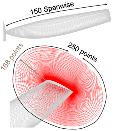
The blades are modelled with three separate grids, shown in Figure 1. The primary gird defines the main body of the blade using the chordwise direction, spanwise direction and surface normal as the three structured grid coordinates. This creates a hollow volume that leaves holes at the root and tip. The tip is covered with a cap grid, while a hub is connected to the root with a collar grid. The viscous sublayer is physically modelled, so the initial surface normal direction spacing is defined by the y+ parameter to include sufficient grid points in high gradient regions. Since the acoustics are sensitive to values in the boundary layer, 168 volume-wise grid points are used in the near-body grids with an end spacing of 10% of the blade reference chord. Likewise, a fine grid spacing of 0.1% of the reference chord length are used for spanwise spacing at the tip to capture the vortex core gradients.
The chordwise spacing uses 0.02% and 0.05% of the reference chord length as spacing at the trialing edge and leading-edge respectively. Since turbulence values are desired near the leading edge, it follows that fine spacing to model the impacting flow at precise locations is important for accurate acoustic predictions. It is equally important to model any flow separation that occurs at the trailing edge. Whether it be from large twist angles or the bluntness of the trailing edge, separation at the trialing-edge is unavoidable. In addition to contributing to self-noise, the separation near the trialing-edge is part of what causes the blade wake, one of the flow structures that leads the noise at the leading-edge of downstream blades.
(a)
(b)
Figure 1: (a) Near body grids and (b) off-body grids.
The off-body grids transmit the near-field flow to the far field, where the freestream boundaries are set. The off-body grid uses 8 levels of refinement, each refinement level doubles in spacing, extending to 20 times the rotor radii, which is necessary to ensure the freestream boundary conditions are met. The level-1, or finest spacing, is 10% of the blade reference chord length and encompasses all near-body grids. The level 1 refinement extends one-quarter of a rotor radii above the rotor plane to model the inflow and turbulence ingestion accurately and 2 rotor radii below the rotor plane to resolve the wake until it naturally dissipates. The second finest refinement, level-2, is typically insufficient to capture vortex gradients due to the grid size having similar magnitude to the vortex core. This leads to artificial vortex dissipation. However, in a forward flight condition where the vortices are convected away from the surfaces, the extent of the level one refinement region should capture any effects that the tip vortices have on the rotor. Level-1 grid spacing finer than 10% can lead to prohibitively expensive simulations, and coarser than 10% will not capture the tip vortices accurately. The large grids in levels 2 and above cannot accurately capture the gradients over the tight core of the vortex and causes them to dissipate artificially.
Similarly, the solver parameters are set to minimize artificial dissipation of vortex structures. A 2nd order dual time-stepping scheme is used to advance the simulation in time yet reduce residuals on each physical time step. The spatial scheme is a 5th order central scheme with rotational correction and delayed detached eddy simulation.
The k-omega shear stress transport (SST) Reynolds Averaged Navier-Stokes (RANS) turbulence model is used to model the flow turbulence that occurs at scales smaller than the grid resolution. This turbulence is key to modeling the leading-edge noise and is defined by two quantities, the turbulence kinetic energy and turbulence dissipation rate. The turbulence integral length scale and turbulence intensity used for the Amiet model can be calculated from the turbulence kinetic energy and dissipation rate. Unsteady RANS solvers are used with the near-body and off-body grids for evaluating the turbulence in the flow field. The flow interaction effects rely on the complex sources near the surfaces, sometimes in close proximity to each other and having coupled effects. The solver must also propagate the flow structures generated in the source regions to the far field with minimal dissipation. Unsteady RANS CFD can capture these effects but require the flow to reach a quasi-steady state where the initial time dependency of the flow startup has passed. This is characterized by near identical flow and forces on a rotor averaged over a revolution. However, due to relative motion of adjacent rotors, the flow structures may differ from one revolution to another.
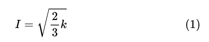
From the converged solution, the turbulence kinetic energy, tke, and dissipation rate, , were extracted from the grids at a small distance in front of the blades leading-edge. From these, the turbulence intensity and integral length scale were calculated using equations 1 and 2 and used in the Amiet model.

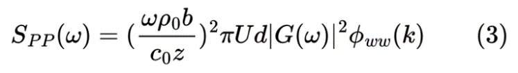
After obtaining appropriate leading-edge values, the implementation of Amiet’s model in UCD-QuietFly was used to predict interactional noise. Leading-edge broadband noise can be caused by the leading edge moving through atmospheric turbulence, as well as the turbulence wakes of other blades or bodies. Amiet’s turbulence ingestion noise at the leading-edge of an aerodynamic lifting surface is expressed in equation 315. The power spectral density of the sound is frequency dependent and can be simplified by assuming the wavelength is small compared to the rotor radius. The turbulence sound contribution is primary modelled in the vertical velocity fluctuations. The term Φww represents the vertical velocity fluctuation spectrum which varies by wave number (k) and is dependent on the Von Karman spectrum and the turbulence integral length scale. The vertical velocity fluctuations attenuate the pressure spectrum along with airfoil lift response (G). The pressure spectrum also scales linearly with the semi-span (d) and velocity (U). The pressure spectrum also increases quadratically with the frequency (ω), freestream density (ρ₀), and chord (b), but decays with the speed of sound (c₀) and distance (z).
Results
The objective of this paper is to evaluate a comprehensive broadband noise prediction including self-noise and leading-edge noise. Leading-edge noise, which is caused by turbulence ingestion, is essential to study the complete broadband noise source of a rotorcraft. First, the aerodynamic flow characteristics are validated. Then the sensitivity of the leading-edge values are measured and used to predict noise.
The acoustic prediction requires the turbulence quantities at along the span of the blade as it makes a full revolution. The CFD solution, which takes 2.5° timesteps is sampled every two steps, or 5° azimuthally. The blade is also sampled at 50 sections radially. This ensures the sound due to different flow characteristic at each span location is properly accounted. The leading-edge index of the near-body grids is found using the principles of structured grids. Then, the distance from the leading-edge is traverse with the volume-wise index near-body grids.
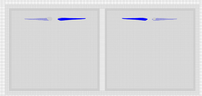
The CFD simulation performance is demonstrated by Figure 2, which shows the coefficient of thrust (convergence and the final revolution averaged thrust compared to the expected experimental value. The plot shows that the simulation converges to 5% of the expected value in three revolutions. The torque coefficient is also within 5% of the expected value. The tip vortices need to be modelled accurately to properly predict the blade wake turbulence, especially near the tip. Figure 3 shows the tip vortices in the wake of the rotors and their trajectory as they are convected downstream. The path of the fore rotor vortices induces turbulence to the inflow of the aft rotor.
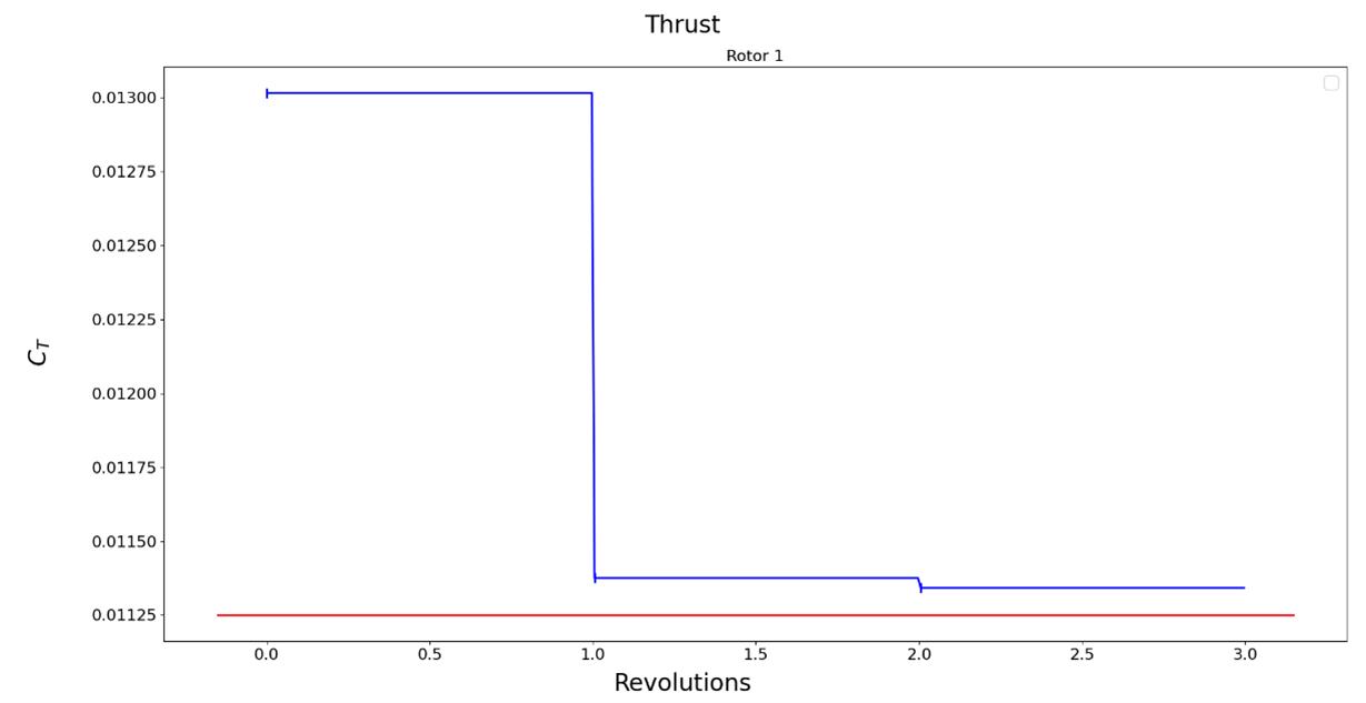
Figure 2: Thrust convergence and validation.
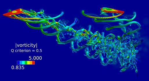
Figure 3: Flow structures of multi rotor vehicle in forward flight.
Figure 4 shows the variation of the turbulence modeling parameters with distance from the blade leading edge at a single blade spanwise location and timestep. Turbulence kinetic energy and turbulence intensity share a similar trend with a peak close to the leading edge and another smaller peak slightly further from the leading edge. Turbulence length has a peak even further from the blades leading edge. Determining the appropriate location to extract the values is critical for accurate noise predictions. A conservative approach was taken and the parameters were extracted at the location where they reached their maximum value.
The turbulence quantities along a rotorcraft’s blade will vary along its span due to increased velocity from the root to the tip and 3D flow effects around the tip. During forward flight, flow conditions will also vary based on the position of the blade. It is then important to consider the flow structures trajectory throughout a revolution. The contour plot in Figure 5 illustrates the turbulence intensity and length scale spanwise and azimuthal changes over the last revolution of a simulation. The trend is similar for both, with increased values are the blade transitions from the advancing side to the retreating side where blade wake interaction is more pronounced.
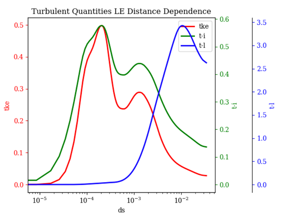
Figure 4: Turbulence quantities varying with distance from leading edge. tke: turbulence kinetic energy, t-i: turbulence intensity, t-l turbulence length
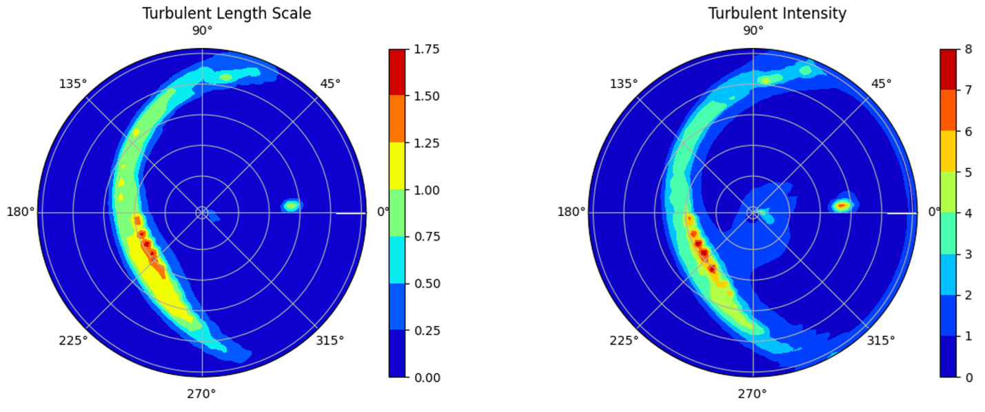
Figure 5: Turbulence quantities varying with space.
The acoustic predictions are carried out on a one-third octave band scale that ranges from 100 to 10,000 Hz, covering a significant portion of human hearing and effective range of the acoustic models. Figure 6 shows the experimental and predicted sound pressure level (SPL) compared. The prediction model only includes broadband noise, thus the noise is underpredicted at lower frequencies where tonal noise dominates. Overall, the shape of the broadband noise signature is captured by the prediction model, but underpredicts.
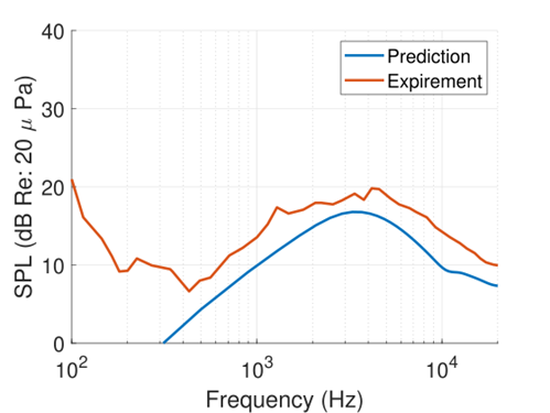
Figure 6: Acoustic prediction comparison with experiment19.
Conclusions
The current work shows the ability to use high fidelity CFD simulations with Amiet’s model for noise prediction. These semi-empirical models are typically applied with low to mid fidelity solutions. The ability to capture 3D flow effects with a RANS model allows physical noise sources to be modelled directly, capturing the predicted turbulence, and using it in the acoustic prediction tools. The use of structured grids simplified the extraction of the turbulence quantities at specific blade relative positions. The turbulence length scale and intensity are shown to peak close the leading edge. Furthermore, the turbulence quantities were shown to represent blade wake interaction in specific regions as the blade completes a revolution.
Future work will quantify how much of rotorcraft broadband noise is created from self-noise and how much of the discrepancy between experiment and prediction is made up for with leading-edge turbulence noise. These same prediction methods will be applied to a variety of geometries including a tilt-wing with closely stacked propellers. This will help evaluate the contributions from interaction noise and noise generated from aerodynamic bodies other than blades, like a downstream wing.
Acknowledgements
I would like to thank my mentor Dr. George Jacobellis, of the Aberdeen Army Research Laboratory. His guidance and support throughout were instrumental to progressing in my research. I am also grateful to the DoD HPC Modernization Program for access to their supercomputers and sufficient computing resources to complete my research, and for the HIP internship.
References
1 Sherman, J. The ((Quiet)) Electric VTOL Revolution. 2020, Vertiflite, Vol. 66, No. 2
2 Swartz, K. I., Transformative Vertical Flight 2020, Vertiflite, Vol. 66, No. 2, 2020, pp. 38–46.
3 Swartz, K. I., The First Electric VTOL Unicorn: Joby Aviation, Vertiflite, Vol. 66, No. 2, 2020, pp. 48–53.
4 Johnson, A. M., Cunningham, C. J., Arnold, E., Rosamond, W. D., and Zègre-Hemsey, J. K., Impact of Using Drones in Emergency Medicine: What Does the Future Hold? Open Access Emergency Medicine, Vol. 13, 2021, pp. 487–498.
5 Balasingam, M., Drones in Medicine – The Rise of the Machines, International Journal of Clinical Practice, Vol. 71, 2017.
6 Esposito, M., Crimaldi, M., Cirillo, V., Sraghini, F., and Maggio, A., Drone and Sensor Technology for Sustainable Weed Management: A Review, Chemical and Biological Technologies in Agriculture, Vol. 8, 2021.
7 Mogili, U. R., and Deepak, B., Review on Application of Drone Systems in Precision Agriculture, Procedia Computer Science, Vol. 133, 2018, pp. 502–509.
8 Ahirwar, S., Swarnkar, R., Bhukya, S., and Namwade, G., Application of Drone in Agriculture, International Journal of Current Microbiology and Applied Sciences, Vol. 8, 2019.
9 Tezza, D., A Modular Framework for Multi-Rotor Unmanned Aerial Vehicles for Military Operations, PhD Thesis, University of South Florida, 2021
10 Bastian, N.D., Fulton, L. D., Mitchell, R., Pollard, W., Wierschem, D., Wilson, R., The Future of Vertical Lift: Initial Insights for Aircraft Capability and Medical Planning Military Medicine, Volume 177, Issue 7, July 2012, Pages 863–869
11 Lee,S., Ayton, L., Bertagnolio, F., Moreau, S., Chong, T., and Joseph, P., Turbulence Boundary Layer Trailing-Edge Noise: Theory, Computation, Experiment, and Application, Progress in Aerospace Sciences, 2021, p. 100737.
12 Brooks, T., Pope, D., and Marcolini, M., Airfoil Self-Noise and Prediction, Tech .rep., NASA, July1989.
13 Amiet, R., “Noise Due to Turbulence Flow Past a Trailing Edge,” Journal of Sound and Vibration, Vol. 47, No. 3, 1976, pp. 387–393.
14 Thai, A., De Paola, E., Di Marco, A., Stoica, L., Camussi, R., Tron, R., and Grace, S., Experimental and Computational Aeroacoustic Investigation of Small Rotor Interactions in Hover, Applied Science, Vol. 11, No. 21, 2021.
15 Amiet, R., Acoustic Radiation from an Airfoil in a Turbulence Stream, Journal of Sound and Vibration, Vol.41, No.4, 1975, pp. 407–420.
16 Paterson, R., and Amiet, R., Acoustic Radiation and Surface Pressure Characteristics of an Airfoil due to Incident Turbulence,” 3rd Aeroacoustics Conference, Palo Alto, CA, July 20-23, 1976.
17 Pulliam, T., High-Order Accurate Finite-Difference Methods: as seen in OVERFLOW, AIAA Paper 2011-3851, June 2011.
18 Chan, W. NASA Ames Research Center Contribution to GMGW-1. 2017, AIAA Geometry and Mesh Generation Workshop, Denver, Colorado
19 Zawodny, N.; Boyd, D. Investigation of Rotor-Airframe Interaction Noise Associated with Small-Scale Rotary-Wing Unmanned Air Systems. Journal of American Helicopter Society. 2020.
Author Biographies
Nikos P. Trembois earned a Master of Science degree in Aerospace Engineering at University of California, Davis where he is currently pursuing a PhD. He entered with an interest in computational fluid dynamics and aeroacoustics and has primarily focused on computational aeroacoustics of rotorcraft. Along the way, he also worked on grid generation. He found grid generation to be a long process that took away from the research which he really refers to spend most time on, so he automated the grid creation process. Through automating the pre- and post-processing steps of CFD, he gained more time for researching aeroacoustics and enabled himself to carry out a wider variety of simulations. He took part in the High-Performance Computing Modernization Program Internship Program internship with the expectation of researching rotorcraft aeroacoustics.
Dr. George Jacobellis received Bachelor’s and Master’s degrees in Aerospace Engineering from The University of Texas Austin. He completed a PhD from Rensselaer Polytechnic Institute in Troy, NY where his research included computational fluid dynamics and vortex particle simulations of high-speed coaxial helicopters. He is now an employee at the U.S. Army Research Laboratory where he continues to work with rotorcraft aerodynamic and acoustic simulations including simulating broadband noise and studying the boundary layers on multi element airfoil configurations.