DECEMBER 2023 I Volume 44, Issue 4
Developing Model-Based Flight Test Scenarios
DECEMBER 2023
Volume 44 I Issue 4
IN THIS JOURNAL:
- Issue at a Glance
- NEW Editor Welcome
- Chairman’s Message
Conversations with Experts
- Memories from a Career in Army T&E: A Conversation with Dr. James J. Streilein
Workforce of the Future
- Workforce Development in Test and Evaluation
Technical Articles
- Tailoring the Digital Twin for Autonomous Systems Development and Testing
- Accelerating Image Recognition Using High Performance Computing
- Developing Model-Based Flight Test Scenarios
News
- Association News
- Chapter News
- Corporate Member News
Developing Model-Based Flight Test Scenarios
Jose L. Alvarado Jr.
AFOTEC Det 5, Edwards AFB, California
![]()

Dr. Thomas H. Bradley
Colorado State University, Ft. Collins, Colorado
![]()
![]()
Abstract
The Department of Defense (DoD) is undergoing a digital engineering transformation in every process of the systems engineering lifecycle. This transformation provides the requirement that DoD Test and Evaluation (T&E) processes begin to implement and begin executing model-based testing methodologies. This paper describes and assesses a grey box model-driven test design (MDTD) approach to create flight test scenarios based on model-based systems engineering artifacts. To illustrate the methodology and evaluate the expected outcomes of the process in practice, a case study using a model representation of a training system utilized to train new Air Force Operational Test and Evaluation Center (AFOTEC) members in conducting operational test and evaluation (OT&E) is presented. The results of the grey box MDTD process are a set of activity diagrams that are validated to generate the same test scenario cases as the traditional document-centric approach. Using artifacts represented in System Modeling Language (SysML), this paper will discuss key comparisons between the traditional and MDTD processes. This paper demonstrates the costs and benefits of model-based testing and their relevance in the context of operational flight testing.
Keywords: T&E, MDTD, AFOTEC, SysML, MBSE, flight test, white box testing, black box testing, grey box testing.
Introduction
The primary objective of DoD T&E is to provide decision-makers with essential information for assessing the suitability of a weapon system for fielding [1]. The T&E community must deliver defensible results that inform senior leaders about system performance and the impact of design parameters on effectiveness and maintainability. Traditional T&E flight test planning, conducted by the U.S. Air Force, follows a systematic, sequential document-centric and human expert-driven approach integrated throughout a system’s acquisition life cycle [2] [3] [4]. Flight test planning ensures the accuracy and reliability of data gathering that meets requirements for verification, validation, and thoroughness of system integration but relies heavily on document-centric procedures, system matter experts’ (SME) process knowledge and technical expertise, and a sequential flow of approvals. Comprehensive safety and test plans detail the technical aspects and logistics necessary to execute and report flight, ground, and laboratory test results for air vehicles, subsystems, and components [1].
While well-established, the current T&E approach suffers from three significant drawbacks: 1) the need for constant manual updates to documents due to ongoing changes throughout the development lifecycle, 2) unwieldy and document-centric communication among stakeholders, and 3) the lack of ability to insert new technology or operational requirements due to the manual updates of documents and the requirement for multiple meetings of SMEs [4]. The process of devising test and safety plans takes place in isolation from the design, development, and operation of the system under test (SUT). This creates interdependent serial processes that result in long timelines for submission and approval, which are resistant to requirement changes. The development of a test plan can involve multiple numbers of SMEs and years of effort. Test products are developed, discussed, and refined through multiple meetings and iterations between SMEs, experienced testers, and operators ensuring all system behaviors are identified and addressed [5]. Experienced test engineers are required to possess intimate knowledge of the system and develop test scenarios that accurately identify the relevant measures of performance/suitability (MOP/S) for achieving mission objectives and conveying information about the system’s structure. However, multiple meetings requiring these experienced engineers drive significant resources and extended timelines. of these experienced test engineers require significant resources, extending timelines and creating isolationist thinking that is resistant to requirements changes. The outcome of these activities is a set of detailed test plans and safety packages, presented in document form, which outlines the resources and test activities planned for the SUT to generate information for decision-makers.
Motivation
Dr. Will Roper, the Assistant Secretary of the Air Force for Acquisition, Technology, and Logistics, emphasized that embracing digital design technologies would lead to a faster, more agile, and more competitive weapons procurement process, departing from the traditional defense acquisition approach [6]. In acknowledgment and response, the DoD released the Defense Digital Engineering Strategy in June 2018, to modernize the entire lifecycle of system design, development, delivery, operation, test, and sustainment within the Department [7]. The flight test community is now charged with integrating model-based software engineering (MBSE) concepts and processes seamlessly as part of a community-wide paradigm shift toward model-based test engineering methodologies [8]. By aligning with MBSE principles, the flight test community seeks to enhance the efficiency and effectiveness of flight testing, gain a deeper understanding of system behavior, and foster better collaboration among stakeholders [6] through model-driven test planning. This transition has the potential to do four things: 1) aid in the management of program complexities by highlighting communication routes and easing data transfer, 2) help in the integration of new technologies and design approaches by enabling data-based decision-making, 3) enable re-planning on the fly to support changing mission scenarios, and 4) support the needs of stakeholders by tracking requirement flow-down [3] [9] [10].
In response to this declared need, this paper presents the creation of an MBSE framework that has been applied to the physical testing of a SUT that creates and defines test scenarios. A simple case study is presented to exemplify the methodology and demonstrate the effectiveness of model-based flight test scenario development.
Background
Model-Based Testing
The MBSE methodology encompasses a range of interconnected processes, methods, and tools that operate within a “model-based” or “model-driven” framework [11]. Various industries, including aerospace and software development, have embraced MBSE methodologies to streamline the creation of complex systems and products including testing [12]. MBSE methodologies create models that are abstract representations of reality [13]. These artifacts can represent various aspects of the desired behavior of a physical SUT. Interconnected state machine diagrams, use-case diagrams, sequence diagrams, and mathematical models allow researchers and testers to generate independent test cases that are decoupled from specific design implementations [14] [15]. The model can be used to further define test parameters and generate the details of a test plan for a given test case, allowing for testing, investigation, and optimization without the use of the physical asset.
Model-Based Testing Techniques
Models serve as essential abstractions of physical systems, enabling engineers to reason effectively by focusing on relevant details while ignoring extraneous complexities. All branches of engineering heavily rely on models to comprehend intricate real-world systems [16]. Model-based testing allows test engineers to concentrate on evaluating software behavior models to determine their acceptability, considering factors like reliability, maintainability, and efficiency [17]. These tests may be developed as a preliminary step before implementing the physical system, or they may stem from an existing or in-development system [16].
This study adopts the philosophies of grey box testing to realize maximum value and compatibility with current operational flight test procedures. In grey box testing, the tester combines the benefits of both black-box and white-box testing. White box testing involves a meticulous examination of the internal logic and structure of the source code, necessitating the tester to possess comprehensive knowledge of the source code and the application’s internal workings [18]. Black box testing is conducted when access to internal design or source code is not possible. Black box testers only understand the intended functionality of the software and have access solely to requirements specifications [18]. Grey box testing combines the benefits of both black-box and white-box testing where the tester possesses limited knowledge of the internal structure or underlying code and understands the fundamental aspects of the system [19]. Furthermore, non-functional testing can be performed to assess various attributes of a system, such as stress testing, which is not directly related to the application’s functions. Non-functional testing can be used to evaluate the system’s readiness [19].
All these types of testing techniques require an underlying process in which the techniques are executed. Among the most common processes used for test case generation from SysML diagrams is coverage criteria. Coverage criteria are defined as the set of conditions and rules enforcing a set of test requirements on a software test to enhance the generation of comprehensive test cases based on the number of elements to cover or visit within a diagram [20]. There are eight common transition-based coverage criteria used in test case generation, of which all-paths coverage specifies that each executable path should be followed at least once and all-configurations coverage is required to visit every configuration of the MBSE models at least once [20].
Leveraging some of these model-based testing techniques and tools to plan flight tests, the T&E community can gain new approaches to better evaluate flight test programs, verify system functionality, ensure compliance with specifications, and ascertain that SUTs can consistently deliver the intended performance in operational scenarios.
The Flight Test Application
Traditional flight testing commences once a program manufactures a representative prototype SUT. During this stage, developmental T&E (DT&E) tests the SUT for integration, interoperability, supportability, safety, and utility [21]. DT&E demonstrates the engineering design and development process is complete, design risks have been minimized, and the system specifications are met [22]. DT&E flight testing is primarily overseen by the Air Force Flight Test Center (AFTC) which assembles and authors comprehensive test plans “to communicate technical detail and logistics required to execute and report results of flight, ground, and laboratory tests of air vehicles, subsystems, and components” [23]. AFOTEC is responsible for conducting integrated operational T&E (OT&E) throughout program development, with dedicated OT&E after the program enters Low-Rate Initial Production [2] [4] [21].
METHODS
Model-Driven Test Design
By leveraging approaches such as MDTD and the capability to isolate and test individual components independently, a powerful approach to optimizing system test design can be realized. Through MDTD, relationships and dependencies that govern the creation of solutions ensure a comprehensive understanding of the repercussions of any changes made at any stage of the process by highlighting the broken relationships [16]. MDTD has demonstrated the ability to aid in efficient testing and significantly enhance the overall development process of software [16]. By embracing MDTD principles, flight test organizations may be able to achieve higher levels of precision and confidence in their testing and development endeavors [19]. Applying MDTD approaches to flight test has the potential to identify a system’s reliability, maintainability, and survivability deficiencies, and allow system designers to correct deficits quickly, thereby enhancing overall system quality [16].
The MDTD process empowers test designers to define tests at higher levels of abstraction by simplifying test generation into a series of tasks. The tasks use mathematical engineering structures to define test values independent of the intricacies of the design artifacts present in the software. The abstraction of the MDTD process allows the early involvement of designers in the test planning process and incorporates the testing into the design [17]. The canonical MDTD process [17] (illustrated in Figure 1 by the smaller black boxes) initiates with a test product, which could be a design element, a SysML model, a user manual, or actual source code within a SUT model [20]. The design artifact can take the form of a graph, logic expression, or a syntax description establishing test requirements [17]. MDTD empowers test designers to “raise the level of abstraction,” [17] allowing a subset of testers to handle the high-level, statistical, and defensibility aspects of test design and development. Traditional testers and programmers can then focus on automating tests, collecting, and measuring values while executing the tests, and evaluating the results. This division of tasks enhances efficiency and effectiveness in the testing process by accomplishing both design and test planning in parallel and enhancing communications between designers and test stakeholders [17].
The flight test planning process can take advantage of the parallelism afforded by the MDTD process directly, as depicted by the yellow boxes in Figure 1. In flight testing, the design artifact can be defined as a requirement, function, or capability that is to be evaluated. Flight test design takes a design artifact under evaluation and develops test scenarios at the design abstraction level. The test scenarios create detailed test plans at the implementation abstraction level that will be executed to collect the data required to evaluate the design artifact. The superimposed process results in test requirements that test the design artifact through the detailed test plan, bridging the gap between the design and implementation abstraction levels.
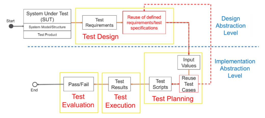
Figure 1: Model-driven test design (black boxes) super-imposed with the flight test planning process (yellow boxes)
Existing Test Scenario Generation Process
At present, flight testing primarily involves authoring comprehensive test cases and safety plans, assembled to effectively communicate the technical details and logistics required for executing and reporting the results of flight, ground, and laboratory tests involving air vehicles, subsystems, and components [24]. The challenge with this established test planning practice is its document-centric approach and the relationships between stakeholders. Successful test planning is based on relationships that are actual human relationships between stakeholders that are difficult to abstract and control. The process requires experienced individuals with in-depth knowledge of the system to create test scenarios. The process is usually accomplished through numerous meetings and iterations to ensure that all air vehicle behaviors are identified and addressed. The relevant MOP/S correspond to the achievement of mission objectives. The MOP/S conveys information about the SUT structure and how it will perform in its operational environment.
Innovative Test Scenario Generation Process
The importance of test scenarios cannot be overstated, as they play a pivotal role in identifying and communicating the conditions to be implemented during testing. They serve as a critical means to verify the successful and acceptable implementation of product requirements [25]. Test scenarios are devised to determine the essential measures (MOP/S) required to verify the successful and acceptable implementation of product requirements [25]. The MOP/S aligns with the mission objectives for the warfighter and provides insights into the system’s structure and usability in the field [5]. Using an MBSE structure through various diagrams, the generation of test scenarios can be realized, facilitating the initiation of the testing process parallelizing with design, and guiding the testing methodology [23].
A practical approach to creating test scenarios can be realized by beginning with the use case diagram to generate scenarios, followed by the activity diagrams to define flows, and finally, the sequence diagrams to provide the detail required by the test plan. By implementing grey box testing techniques borrowed from software implemented within an MBSE construct, the result provides an alternative to the document-centric test planning process. The process is illustrated in Figure 2. As a result, these diagrams guide developers in designing the system and provide testers with essential information for conducting thorough testing [23].
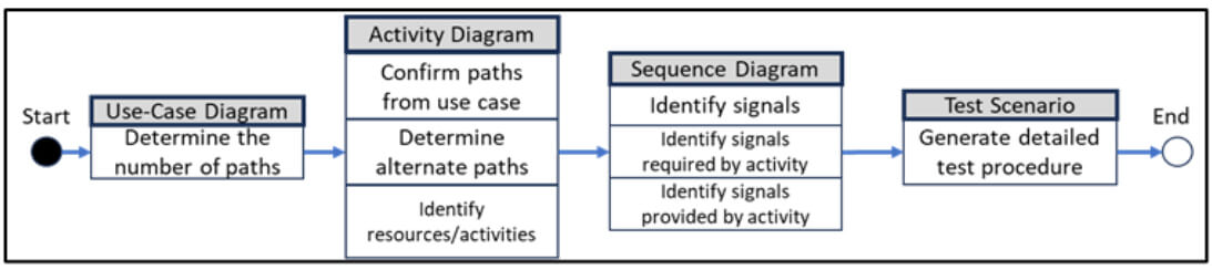
Figure 2: Grey Box Implementation of the Test Scenario Generation Process
Borrowing from the MDTD process and using the grey box test scenario generation process illustrated in Figure 2, along with the use case diagram depicted in Figure 4, a basic flow can be generated using the use case diagram to model a series of dialogs. The generation of test scenarios relies significantly on the flow of events, which can be divided into two parts: the main flow of events and the alternate flows of events that can be extracted from either the use-case or activity diagram. The main flow of events represents the “normal” happenings when the task is performed, while the alternate flows of events encompass optional or exceptional case flows relative to normal behavior [20]. Some alternate flows may return to the basic flow of events, while others designated as exceptions may reach an endpoint. Both the basic flow of events and the alternate flows can be further organized into steps or sub-flows [25]. To fully specify a use case and define the flows between the system and its actors, a SysML diagram requires a significant amount of detail. These details can be developed into steps, explaining the actions of both the actor and the system in response that are realized in the number of unique test scenarios [25].
Test scenarios are then designed using a structured and practical approach that explores the input space with minimal overlap. Reduction in overlap aids in cost reduction by maximizing the effectiveness of tests [17]. Using the coverage criteria approach and a proper SysML model with sufficiently detailed use-case, activity, and sequence diagrams, we can apply coverage criteria techniques to derive test scenarios.
Case Study Using Grey Box Test Scenario Generation Process
To execute and assess the proposed MBTD processes, the following case study was produced using SysML implemented in MBSE with the Dassault Systems’ Cameo Systems Modeler™ software package following the process illustrated in Figure 2. The case study model was created from a design and development point of view that did not consider any inputs from the testing community. The model was developed by one person over approximately four months using the system description document (SDD), capability design document (CDD), and initial capabilities document (ICD) products, while the document-centric test plan and its associated process required multiple SMEs and a timeline of approximately a six months to accomplish.
This case study focuses on AFOTEC’s Combat Search and Rescue Locator (CSARL) system. CSARL is a fictional system that has been developed as a training case for flight test personnel learning to create test plans. It is well documented and has a thorough reference test plan that has been redeveloped, and this study will serve as an example system upon which to demonstrate the proposed methods for flight-test relevant test plan generation. Since the system is well documented and all AFOTEC personnel are familiar with the material, it makes a good benchmark for applying the grey box-inspired testing technique implemented in an MBSE environment to create a flight test scenario procedure without direct SME intervention. Moreover, it provides a means to compare outputs between the model-centric and document-centric processes.
The SUT for the case study is the CSARL system which is a portable hand-held Global Positioning System (GPS) receiver system offering enhanced digital moving maps and real-time navigational capabilities for downed aircrew and search and rescue (SAR) forces during combat and peacetime survival scenarios. Its purpose is to complement current GPS-integrated survival radios, enhancing existing survival and rescue navigation capabilities without relying on traditional map-and-compass techniques [26]. Documentation used in planning and testing the system, such as the CDD, ICD, SDD, and detailed test plan (DTP) illustrate the existing test scenario generation process. Figure 3 is an excerpt from the document-centric DTP and shows the table of contents highlighting the major headings of the information contained in the document.
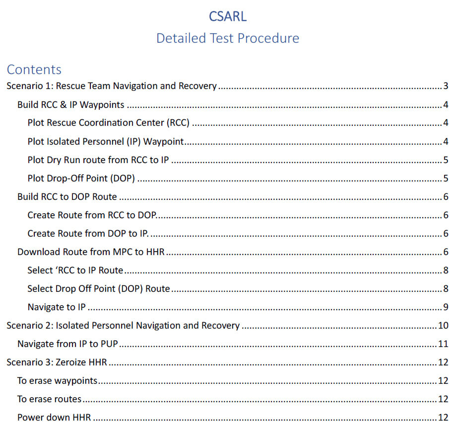
Figure 3: Excerpt of Table of Contents from CSARL Detailed Test Plan.
To implement the MBSE approach, a SysML model was created using the Dassault Systems’ Cameo Systems Modeler™ software to represent the existing CSARL system and incorporate the system requirements from the SDD and descriptions defined in the ICD and the CDD. Figure 4 depicts the system’s use case diagram, and Figure 5 and Figure 6 illustrate the activity and sequence diagrams, respectively.
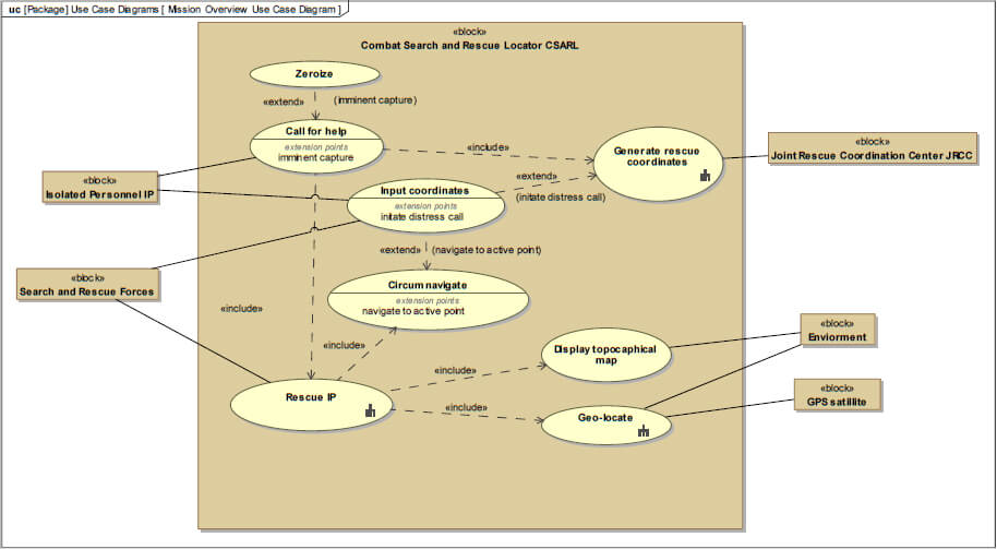
Figure 4: SysML Use Case Diagram of the Combat Search and Rescue Locator (CSARL) system used in the Case Study.
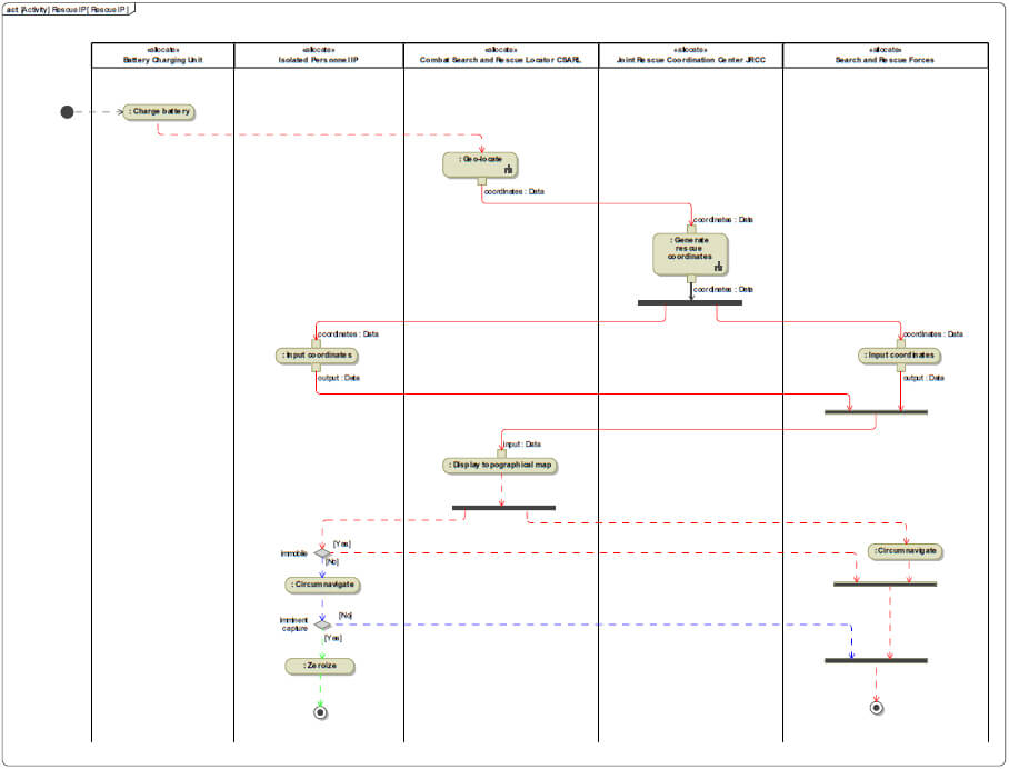
Figure 5: SysML Activity Diagram of the Combat Search and Rescue Locator (CSARL) system used in the Case Study with Identified path flows.
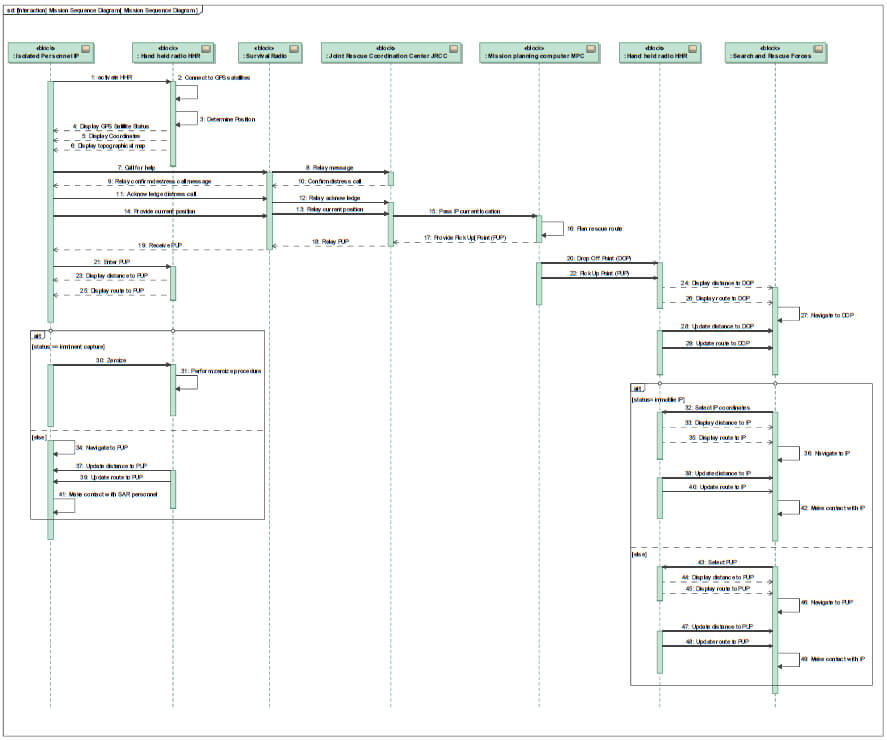
Figure 6: SysML Sequence Diagram of the Combat Search and Rescue Locator (CSARL) system used in the Case Study.
The interaction between the SUT and people engaged in the process (actors) [25] is documented in an activity diagram (Figure 5). The dialogs explain the actor’s inputs or actions and the system interactions that are created in response [25]. For our CSARL example, the primary or basic flow is illustrated by the red path in Figure 5, which diagrams the situation where an aircraft experiences a critical mechanical failure, and the aircrew must eject.
The basic flow designates the aircrew as being injured and immobile and can be summarized as:
1. Call for help: The aircrew, now designated as isolated personnel (IP), initiates a call for help and provides secured GPS coordinates.
2. Generate Rescue Coordinates: The Joint Rescue Coordination Center (JRCC) authenticates the IP, relays the status, location information, and directs the search and rescue (SAR) forces to the IP’s location.
3. Input coordinates: The SAR forces team enters pre-designated point(s) where the IP has indicated where they are located.
4. Circumnavigate: The SAR forces circumnavigate to the designated IP coordinates for rescue and extraction.
In our CSARL case study, we have two alternate flows that can be executed, one by the aircrew personnel or IP and the other by the SAR forces. The first alternate flow designates the aircrew as able-bodied, having the ability to proceed to a designated pick-up point (PUP). Alternate flow 1 is illustrated by the blue path in Figure 5. The scenario is described as the JRCC directs both the IP and the SAR forces to a designated PUP coordinate where both parties circumnavigate for rescue and extraction. The second alternate flow is the case of imminent capture of the aircrew where they must perform a zeroize procedure that renders the handheld radio (HHR) inoperative. This is shown as the green path in Figure 5.
Once all flows have been identified in the SysML activity diagram, a table of all possible flows is created by applying the all-paths and all-configurations coverage criteria to generate all possible combinations using the grey box test scenario generation process and the basic flow and each alternate flow. For our example, Table 1 lists all the generated possible flows and configurations. Figure 7 illustrates the grey box test scenario generation process by using scenario 1 from Table 1 to generate the test procedure that outlines the steps required to execute the SAR team circumnavigation to IP test case.
Table 1: All configurations of flows are arranged into various scenarios.
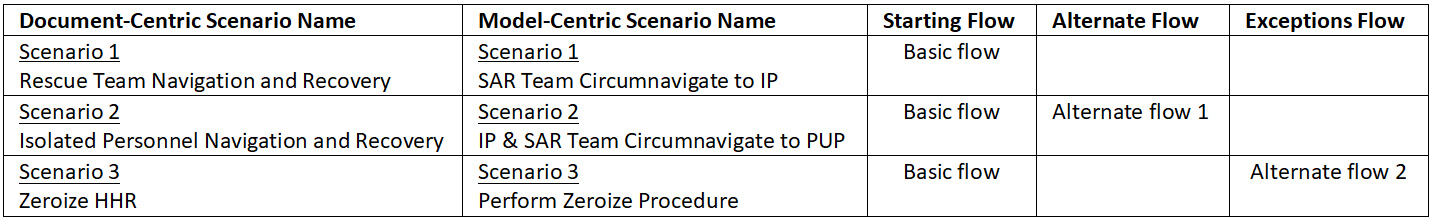
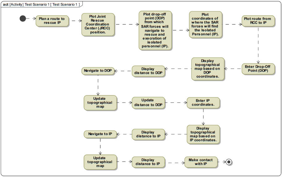
Figure 7: Activity diagram of Scenario 1 illustrating the test procedure that outlines the steps required to execute the SAR Team Circumnavigate to IP test case.
The case study illustrates that employing an MBSE framework in tandem with specific grey box testing techniques makes it possible to construct test scenarios efficiently. These generated test scenarios can then be seamlessly integrated into comprehensive test plans aimed at evaluating a system’s capabilities [17]. The case study also shows the SysML model can effectively fulfill the need for well-defined documents outlining test scenarios tailored to the flight test objectives mandated by the acquisition process. Furthermore, the MDTD process can produce these essential documents with a level of reliability equal to the current document-centric method, yielding comparable elements crucial for successful testing [18]. The case study underscores the proposed approach as a viable method for generating test scenarios that contribute significantly to the test planning process.
Results and Discussion
This case study now allows a comparison between document-centric and model-centric processes.
Comparison of Processes using Coverage Criteria
The results of the model-based test scenario-generating method show that this method is effective in creating detailed test scenarios for use in the generation of detailed test plan documents (DTPs)[ Because the federal acquisition regulations (FAR) process is dictated by law, any new flight test process must create the equivalent documents for review and signature approval process required by the federal acquisition regulations, including the DTPs that are the output of this process. ]. Comparing the results between the document-centric and model-centric processes reveals that the model-based method generates a comparable number of test scenarios as the document-centric process as illustrated by contrasting the contents of Table 1 with the table of contents from the DTP illustrated in Figure 3. Similarities in output between the model-based test scenario approach and the document-centric approach provide confidence that both processes can generate similar documentation for testing SUTs.
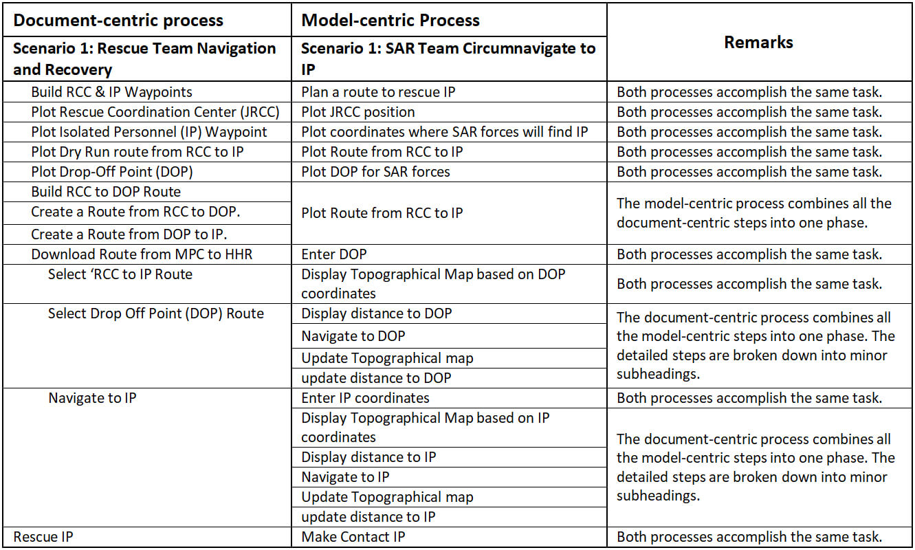
Comparing the subheadings from the table of contents in the training DTP shown in Figure 3 with the steps outlined in the activity diagram in Figure 7, it is evident the model-based test scenario-generating method produces similar steps and content to the document-centric process. All the required steps from the training DTP have been accounted for and there is sufficient detail presented in the SysML activity diagram (Figure 7) to generate a detailed DTP. As illustrated in Table 2, there is a simple and defensible mapping between the DTP steps generated from each process. Although the number of DTP steps and their level of detail is higher in the results of the model-centric process, Table 2 illustrates that the completeness and coverage of the model-centric test development process can be validated relative to the document-centric test development process.
Table 2: Scenario 1 Comparison of the document-centric DTP steps with the model-centric process-generated steps derived from the SysML activity diagram.
Because the federal acquisition regulations (FAR) process is dictated by law, any new flight test process must create the equivalent documents for review and signature approval process required by the federal acquisition regulations, including the DTPs that are the output of this process.
Using Design-centric Models for Test Planning
Although the testing plans that are developed using the document-centric and model-centric approaches both define the same testing tasks, the model-driven process is not free of faults. Because the MBSE model that was developed to represent CSARL was built from a design perspective, it does not represent every connection that would be important from a testing and evaluation point of view. For example, Figure 5 illustrates two alternate flows: 1) test scenario 2: IP & SAR Team Circumnavigate to PUP, and 2) test scenario 3: Perform Zeroize Procedure. Focusing on test scenario 3, Figure 6 confirms that the alternate flow exists but it does not provide details about the zeroing process. A comparison between the subheadings in the document-centric training DTP (Figure 3) and the steps in the model-centric process (Figure 6) demonstrates that the SysML activity diagram lacks sufficient detail to generate a detailed DTP for this case. A SysML activity diagram (Figure 8, which outlines the steps required to perform the zeroing process) is contained in the model but this activity diagram is not explicitly referenced in the activity diagram of the CSARL system (Figure 5).
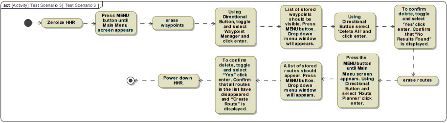
Figure 8: Activity diagram of Test Scenario 3 illustrating the test procedure that outlines the steps required to execute the “Perform Zeroize Procedure”.
The explicit reference for the zeroing process shown in Figure 8 should be shown as a fork in the zeroize task contained in the Figure 5 activity diagram. Links in models are created by the model designer. In the case study, the model designer approached the model design from the development perspective without tester input.
The lack of tester input and review of the model leads to a lack of connectivity between the activity diagrams. Testers with knowledge of the SUT and MBSE software are essential to provide oversight and input into the creation of the models. These testers serve as a quality control check to verify that all information required to produce quality test plans is available and documented in the model. Although the model-based approach has the potential to eliminate the need for multiple SMEs and multiple meetings in developing detailed test plans, the process must create written DTP documents that are controlled for quality through something like the traditional, expert-driven signature process.
Conclusions
The CSARL case study example shows that the novel innovative grey-box test scenario generation process can create the required documents at the same fidelity as the document-centric process [15] [18]. The case study shows the potential for efficient and valid use of SysML models for test plan design with MBSE and MDTD [11]. The use of MBSE and grey box testing realize the promise of digital transformation and constitutes a stride toward modernizing testing methodologies to enhance system evaluation and validation [17] [20]. The CSARL case study exemplifies how adopting the MBSE method aids in the formulation of test scenarios and can contribute to comprehensive test plans for assessing a system’s capabilities [20]. This enhancement can aid in the expedited development of test scenarios [18] [19] by being responsive to mission changes and technology changes that usually occur during a SUT acquisition life cycle. Embracing the paradigm shift toward MBSE in flight test planning provides progress toward the successful implementation of DoD’s Defense Digital Engineering Strategy [3] [9].
This exercise also provides evidence to support the idea that MBSE and MDTD do not replace the human element in test planning since the quality of the output is dependent on the test relevance and completeness of the model which must be checked by capable personnel. This insight empowers testers to engage earlier in the architectural and design aspects of the model development [27]. Implementation of MBSE and the concurrent generation of a testing and operational evaluation model allows for the tester to embed testing information in the model of a SUT. Flight test planning and operational test planning can then occur without the physical asset, allowing test development earlier in the acquisition life cycle. Moreover, the creation of a digital test model leads to a digital test artifact that can be incorporated into a larger life-cycle model to capture the importance and value of flight and operational testing [11].
Acknowledgments
I would like to thank Dr. J Shelley, a co-worker and adjunct faculty member from California State University, Long Beach Antelope Valley Engineering Program, whose countless hours of listening and reading multiple revisions helped me define, organize, and consolidate all the information in this document. Your dedication to my endeavor is greatly appreciated.
References
[1] AcqNotes. AcqNotes Program Management Tool for Aerospace. AcqNotes LLC, 24 7 2021. https://acqnotes.com/acqnote/acquisitions/evolutionary-acquisitions. (Accessed 28 6 2022).
[2] Axiotis, Greg, 2009. A new alpha-omega map for acquisition test and evaluation. The Journal of Test and Evaluation, vol. 30, no. 4, pp. 473-480.
[3] Collins, Christopher, and Kenneth Senechal, 2003. Test and Evaluation as a Continuum. The Journal of Test and Evaluation, vol. 44, no. 1.
[4] Greer, Edward, 2010. The integrated T&E continuum is the key to acquisition success. The Journal of Test and Evaluation, vol. 31, no. 4, pp. 443-444.
[5] Wu, Quentin, and David Gouyon, Eric Levrat, 2021. Maturity assessment of systems engineering reusable assets to facilitate MBSE adoption. IFAC-PapersOnLine, vol. 54, no. 1, pp. 851-856.
[6] AFOTEC A-2/9. Air Force Operational Test and Evaluation Center Test Design Guide. AFOTEC, Albuquerque, 20 July 2018.
[7] Roper, Will. There is No Spoon: The New Digital Acquisition Reality. Department of the Air Force, Washington D.C., 2020.
[8] Office of the Deputy Assistant Secretary of Defense for Systems Engineering. Digital Engineering Strategy. Department of Defense, Washington D.C., 2018.
[9] Air Force Digital Transformation. https://usaf.dps.mil/teams/afmcde/SitePages/Functional-Speciality—Test-and-Evaluation.aspx. (Accessed 28 5 2022).
[10] Henderson, Kaitlin, and Thomas McDermott, Alejandro Salado, 2023. MBSE adoption experiences in organizations: Lessons Learned. Systems Engineering, p. 26.
[11] Henderson, Kaitlin, and Tom McDermott, Eileen Van Aken, Alejandro Salado, 2023. Towards Developing Metrics to Evaluate Digital Engineering. Systems Engineering, vol. 26, no. 1, pp. 3-31.
[12] Borky, John M, and Thomas H. Bradley, 2018. Effective model-based systems engineering. Springer.
[13] Friedenthal, Sanford and Alan Moore, Rick Steiner, 2014. A practical guide to SysML: the systems modeling language. Morgan Kaufmann.
[14] Gregory, Joe, and Lucy Berthoud, Theo Tryfonas, Alain Rossignol, Ludovic Faure, 2020. The long and winding road: MBSE adoption for functional avionics of spacecraft. Journal of Systems and Software, vol. 160, p. 110453.
[15] Wang, Yiwen, and Mao Zheng, 2012. Test case generation from UML models. In 45th annual Midwest Instruction and Computing Symposium, Cedar Falls.
[16] Mussa, Mohamed, and Samir Ouchani, Waseem Al Sammane, Abdelwahab Hamou-Lhadj, 2009. A Survey of Model-driven Testing Techniques. In 2009 Ninth International Conference on Quality Software.
[17] Beydeda, Sami, and Matthias book, Volker Gruhn, 2005. Model-Driven Software Development. Springer, Germany.
[18] Ammann, Paul, and Jeff Offutt, 2016. Introduction to Software Testing. Cambridge University Press.
[19] Jan, Syed Roohullah, and Syed Tauhid Ullah Shah, Zia Ullah Johar, Yasin Shah, and Fazlullah Khan, 2016. An innovative approach to investigate various software testing techniques and strategies. International Journal of Scientific Research in Science, Engineering and Technology (IJSRSET), Print ISSN, vol. 23951990.
[20] Bansal, Anju, 2014. A Comparative Study of Software Testing Techniques. International Journal of Computer Science and Mobile Computing, vol. 36, no. 6, pp. 579-584.
[21] Salman, Yasir Dawood, and Nor Laily Hashim, Mawarny Md Rejab, Rohaida Romli, Haslina Hohd, 2017. Coverage criteria for test case generation using UML state chart diagram. In AIP Conference Proceedings.
[22] AcqNotes. AcqNotes Program Management Tool for Aerospace. AcqNotes LLC, 21 4 2021. https://acqnotes.com/acqnote/careerfields/operational-test-and-evaluation-ote. [Accessed 28 5 2022].
[23] AcqNotes. AcqNotes Program Management Tool for Aerospace. AcqNotes LLC, 5 4 2022. https://acqnotes.com/acqnote/careerfields/development-test-and-evaluation. [Accessed 13 11 2022].
[24] Van Peteghem, Gerry, and Christpher J. Liebmann, Stephanie S Mailen, Jeffrey D Martin, Kevin L. Peck, 2021. Test Plan Author’s Guide. Engineering Directorate, 412th Test Wing, Edwards AFB.
[25] AcqNotes. AcqNotes Program Management Tool for Aerospace. AcqNotes LLC, 19 12 2021. https://acqnotes.com/acqnote/acquisitions/emd-phase. [Accessed 28 5 2022].
[26] Mohd, Ehmer Khan, and Farmeena Khan, 2012. A comparative study of white box, black box, and grey box testing techniques. International Journal of Advanced Computer Science and Applications, vol. 3, no. 6, p. 4.
[27] Heumann, Jim, 2001. Generating test cases from use cases. The rational edge, vol. 6, no. 01.
[28] Director of Operational Capability Requirements, 2018. Capability Development Document (CDD) for Combat Search and Rescue Locator (CSARL). Washington D.C.: Department of Defense.
[29] INCOSE, 2015. INCOSE Systems Engineering Handbook: A Guide for System Life Cycle Processes and Activities. New Jersey: Wiley.
Author Biographies
JOSE ALVARADO is a senior test engineer and system analyst for AFOTEC at Edwards AFB, California with over 33 years of developmental and operational test and evaluation experience. He is a Ph.D. candidate in the Systems Engineering doctorate program at Colorado State University with research interests in applying MBSE concepts to the flight test engineering domain and implementing test process improvements through MBT. Jose holds a B.S. in Electrical Engineering from California State University, Fresno (1991), and an M.S. in Electrical Engineering from California State University, Northridge (2002). He serves as an adjunct faculty member for the electrical engineering department at the Antelope Valley Engineering Program (AVEP) overseen by California State University, Long Beach. He is a member of the International Test and Evaluation Association, Antelope Valley Chapter.
THOMAS H. BRADLEY, Ph.D. serves as the Woodward Foundation Professor and Department Head for the Department of Systems Engineering at Colorado State University. He conducts research and teaches a variety of courses in system engineering, multidisciplinary optimization, and design. Dr. Bradley’s research interests are focused on applications in Automotive and Aerospace System Design, Energy System Management, and Lifecycle Assessment. Bradley earned the BS and BS in Mechanical Engineering at the University of California – Davis (2000, 2003), and the PhD in Mechanical Engineering at Georgia Institute of Technology (2008). He is a member of INCOSE, SAE, ASME, IEEE, and AIAA.