DECEMBER 2023 Volume 44, Issue 4
Tailoring the Digital Twin for Autonomous Systems Development and Testing
DECEMBER 2023
Volume 44 I Issue 4
IN THIS JOURNAL:
- Issue at a Glance
- NEW Editor Welcome
- Chairman’s Message
Conversations with Experts
- Memories from a Career in Army T&E: A Conversation with Dr. James J. Streilein
Workforce of the Future
- Workforce Development in Test and Evaluation
Technical Articles
- Tailoring the Digital Twin for Autonomous Systems Development and Testing
- Accelerating Image Recognition Using High Performance Computing
- Developing Model-Based Flight Test Scenarios
News
- Association News
- Chapter News
- Corporate Member News
Tailoring the Digital Twin for Autonomous Systems Development and Testing
Dennis Bergin, Ph.D
DCS Corporation
William (Leighton) Carden
DCS Corporation
Kevin Huynh
DCS Corporation
Parth Parikh
DCS Corporation
Paul Bounker
U.S. Army Ground Vehicle Systems Center
Burhman Gates
U.S. Army Engineer Research and Development Center
John Whitt
U.S. Army Aberdeen Test Center
Abstract
While the use of digital twins for developing and testing of systems and subsystems is fairly common practice, the use of digital twins for the development and testing of autonomous systems is a relatively emerging concept. In reality, what is being tested is the machine’s ability to perform specific functions. Some of these functions are done in a similar manner as humans do them, while others use a different approach. For example, building machine versions of human anatomy, senses, intuition, and learning capabilities is a difficult task. Therefore, the digital twins must be focused on modeling and simulating the environment not so much as the human perceives it, but as the machine perceives it. This paper goes into detail on testing autonomous system task performance in the context of driving a Palletized Load System (PLS). This paper goes into detail on the considerations and developments that allow testers to inject faults, weather, and obstacles to stimulate the autonomy under test designed to replace the human driver.
Background
A need to test autonomous ground vehicles virtually was identified by the U.S. Army Aberdeen Test Center (ATC)1, a subordinate command of the U.S. Army Test and Evaluation Command (ATEC). To do this, a Systems Integration Lab (SIL) was stood up along with providing a virtual leader to the Roadway Simulator, running thousands of scenarios on high performance computers (HPC) and Virtual Leader/Live Follower testing.2 Building a SIL is an established practice for systems integration, using it for the testing of autonomous systems is somewhat more challenging. Integration requires simulation or emulation that stimulates the autonomy sensors and basic vehicle functions. To test the system, the simulation must accurately model the environment or areas of testing concerns. This paper will identify fault areas and environmental conditions for Palletized Load System (PLS) and the Leader/Follower program. This program uses a manned leader and then requires the follower vehicle to autonomously follow at a defined distance or time, while stopping for any obstacles that should enter the defined path of the follower. The scope of the paper covers autonomous ground vehicles as well as autonomous convoys. Weaponized unmanned ground vehicles and unmanned aerial vehicles will not be addressed. It will specifically address the use of digital engineering tools to test autonomous systems not the development phase although that is an additional benefit.
Purpose
The purpose and intent of this paper is to educate readers on current testing procedures and tools for autonomous ground vehicles. This paper will also describe a methodology that will be employed by ATEC to test future autonomous systems to ensure live testing readiness and to inform an efficient set of live testing scenarios to fully characterize autonomous system capability. They are ready for live testing. This is primarily a need because ATC and ATEC were getting autonomous systems for testing just weeks before they were needed to support soldier demonstrations. ATEC is responsible for writing safety releases on systems to support these demonstrations as well as safety confirmations to support fielding. Due to the short timeframe and limited funding, the complete list of scenarios to fully vet these systems could not be executed. As a result, these systems could not be completely assessed and caution had to be used
when writing safety releases. In May 2020, a project called the Autonomous Systems Test Capability (ASTC) began execution to develop the tools necessary to meet this need. It is approximately a $16 million project funded by the DoD Test Resource Management Center as part of their Central Test and Evaluation Investment Project Portfolio. The project was in development for two years and completed development in December 2022.
Methodology
ASTC uses a virtual environment that allows ATEC to test the decision making of the autonomous software on autonomous systems in a virtual environment. This testing approach utilizes distinct methodologies to maximize what can be tested in a virtual world. The first part of virtual testing is to create digital visual and mechanical twins for the terrain, the vehicle with characteristic mobility, sensors, and a harness in which to integrate the autonomous software under test. In this case, we used a 3D computer graphics game engine named Unreal Engine (https://unrealengine.com) to integrate all of the components. Figure 1 is a PLS operating on a digital twin of the Aberdeen Test Center’s high speed test track.3
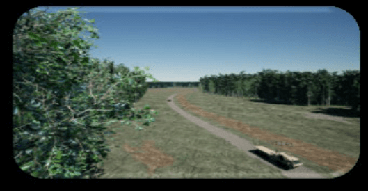
Figure 1: PLS Driving on a Digital Twin of ATC’s High Speed Test Track
SIL Development
SIL’s are a great way to validate that code is working as planned and that defined subsystems are communicating and sharing agreed upon interfaces as designed. SILs consist of software under development running on copies of hardware planned for the vehicle or suitable surrogates. Figure 2 shows the Autonomous Systems Test Capability SIL. Simulation or stimulation is used to move the software through the expected functional states to validate that the software operates under design guidelines. For example, if the autonomy software is expected to command the vehicle to move, then a mobility component is simulated or emulated that responds to autonomy software commands in a similar manner as the actual vehicle does, with the planned associated or corresponding responses sent back to the autonomy software.
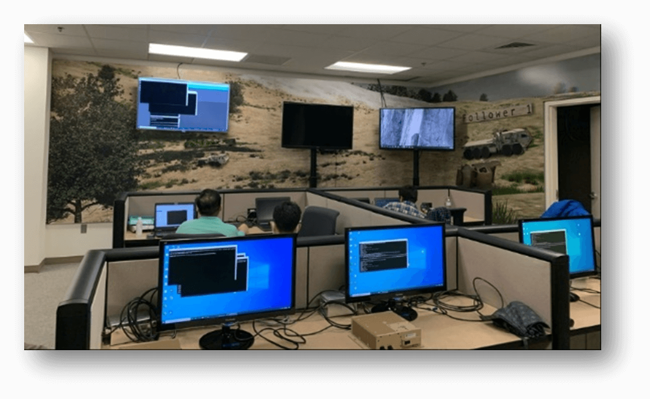
Figure 2: Autonomous Systems Test Capability SIL
Autonomy Under Test
Autonomy or Artificial Intelligence/Machine Learning can perform a myriad of functions from relatively simple things, like running a toaster or coffee machine at a programmed time, to far more complex tasks. The example used in this paper is that of driving as a PLS follower, as part of a military convoy with a specific definable (within set boundaries) mission with associated following procedures and gap distances. This is a complex set of military task(s) and subtasks based on the overall military mission description.
The first thing that must be done is an analysis on how the overall autonomy software functions including the relevant inputs and outputs of the software. The Follower(s) receive convoy instructions along with specific vehicle information, such as speed and acceleration at specific locations, from the leader. Therefore, the SIL must consist of two or more vehicles or recordings of a Leader from geo-specific range that have been digitized. The specific data can be sent using standard computer messaging paradigms to stimulate the autonomy software. Section 3.5 describes modifying the data sent from Leader to Follower in a realistic manner to emulate radio performance as seen in the field to test responses to potential error conditions.
Upon receiving suitable instructions, the autonomy software receives data from on-board sensors, such as Global Positioning System (GPS), to identify when the gap distance is sufficient for the vehicle to be commanded to move. The autonomy software will receive specific data from modeled Light Detection and Ranging (LiDAR) sensors to make certain that it is safe to move in the commanded direction at this time. Assuming no obstacles are detected, a command is sent from the Autonomy software to a mobility simulation that models the movement of the vehicle. The new location from the mobility model is provided to the GPS emulation which then changes the location of the follower, and this change then reflects potential new instructions from the autonomy software based on current location compared to the leaders and specific updated data from the LiDAR subsystem. Sections 3.6 and 3.8 describe modifying LiDAR data in a realistic manner to test responses to potential error conditions.
The Autonomy Under Test in the Leader/Follower example is called the Autonomy Kit (A-Kit). There is also a By-Wire or (B-Kit) which takes requests from the A-Kit and provides the necessary signals to the actual vehicle to move it in the direction and speed requested by the A-Kit. The B-Kit is emulated in the SIL, since creating detailed real-time models of vehicle systems is a detailed and costly process. The emulation keeps the A-Kit running as it normally does and allows for detailed testing in a lab environment. B-Kit testing is accomplished through a Hardware-in-the-Loop simulator, the ATC Roadway Simulator, which is a treadmill for military vehicles. The belts on the simulator move and so do the wheels but it doesn’t go anywhere. It can simulate the vehicle turning as well. With the help of simulators like this, autonomous convoys can be tested with just one live vehicle. A digital twin virtual leader can be used to interact with a live follower and potentially other virtual followers. The live follower thinks it’s on a road somewhere following the lead vehicle but in reality, it is on a simulator. Below are pictures illustrating this capability where a person drove the virtual leader on a digital twin of the Perryman 3-mile test track at ATC while sending location breadcrumbs to the live follower on the roadway simulator, in December of 2021. The pictures also illustrate the injection of a deer into the digital twin and the live follower responding appropriately by stopping. This was accomplished by turning off the sensors on the live follower and instead feeding it sensor stimulation feeds from the virtual scenario.
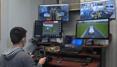
Figure 3: Virtual Leader Commanding a Live Follower on the Roadway Simulator
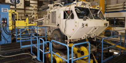
Figure 4: PLS on the Roadway Simulator
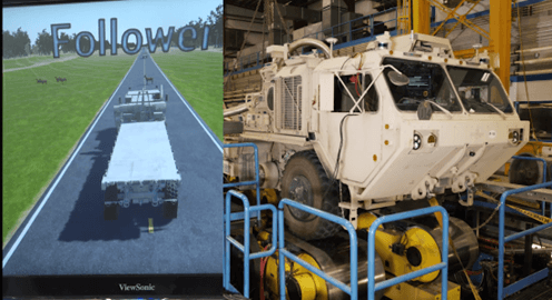
Figure 5: Live Follower Stopping After Interacting With A Virtual Deer
Simulation /Stimulation
Simulation is the effect of modeling a system or subsystem over time. Stimulation, provides an input or response to a software system or subsystem to assist in testing functionality. In A-Kit testing both simulation and stimulation are used. Inputs to the key functions to the A-Kit’s performance are simulated. These include such things as LiDAR, which is one of the key inputs to determine how the A-Kit responds to specific scenario conditions and as such should be modeled accurately including any performance variations due to the effects of the operating environment. LiDAR is sensitive to environmental conditions such as rain, snowfall, fog, and dust. Section 3.8, Weather Effects on LiDAR Simulation, describes the weather effects in a realistic manner for testing and evaluation of the A-Kit software functionality. Stimulation is used to replicate certain subsystem functions necessary for keeping the A-Kit operating as it normally does while simulated subsystems perform detailed performance testing. One such stimulated subsystem on the Leader/Follower is the Navigation Box (Nav Box) which performs localization for the vehicle. Localization is where the vehicle believes it is, based on inputs from GPS, Inertial Motion Unit (IMU), wheel encoders, and Terrain Registration inputs. The calculated position, gap distance goals, and information from the Leader are used to assist the A-Kit in determining what direction and speed recommendations to provide to the B-Kit.
Fault Injection
It is very beneficial for a SIL to be able to test responses of the autonomous vehicle to abnormal simulated or stimulated input data to analyze vehicle behavior for safety purposes. This can be accomplished by injecting faults into a specific subsystem such as the A-Kit, B-Kit or navigation system. Examples of pertinent faults are vehicle faults or faults related to the engine, powertrain, suspension, power system, steering, braking, or the wheels and tires. Air brake pressure could be of great interest as it may affect the gap distance between multiple vehicles in a leader follower scenario. It would be beneficial to analyze how the A-Kit would react to losing air brake pressure and to characterize the resulting ‘exceptions’ to the gap distance rules under certain circumstances, such as moving through “hilly” regions.
It is important to support both time-based and event-based fault injections. Time-based faults provide testers with a fine level of control and allow for consistency and repeatability. Event-based fault injection supports more dynamic injections. Additional types of useful fault injections would be to degrade sensor data such LiDAR data or to degrade communications between the vehicle and external systems. Both are discussed further in section Sections 3.5 and 3.6.
COMMS Degration Fault Injection
To test communication degradation, the SIL allows us to view how data can be modified through radio performance from Leader to Follower vehicle. This can be accomplished by sending a message/injection from the Fault server to the Comms application. These messages communicate which traffic control command needs to be executed on the network. By executing these messages, data on the network will be modified due to the various types of packet manipulation that is present, such as packet loss, duplication, delay, and bandwidth.
As previously mentioned, we can validate that the code is working by stimulating certain inputs to observe how the vehicles would react. For example, if we were to send a message for a %100 packet loss, we can see that the vehicle will come to complete stop for a brief moment because it is not receiving any data from its radios. By having the capability to repeatedly test different types of messages, it gives us more control over the radio performance between the vehicles and the ability to respond to different error conditions in the field.
Lidar Fuzzing Fault Injection
To simulate realistically degraded LiDAR feeds to observe the effects this degraded performance has on autonomy controllers, we engage in a practice called LiDAR Fuzzing. LiDAR Fuzzing is achieved at a network interface level by using a service to intercept incoming LiDAR data as a raw stream, modify it to some testing level, and then forward the modified LiDAR on to its original destination. Modifications for simulating faults are most often semi-random disruption patterns applied as a mask to the point cloud data in real-time. The LiDAR Fuzzing Service can control what percentage of overall points are disrupted and is able to communicate with the Fault Service described in Section 3.7 to report and change its state. By performing this real-time modification, we are able to observe how adverse conditions like heavy environmental particulates or even signal noise can interfere with the behavior of the autonomy controller.
As the LiDAR Fuzzing is a real-time operation, validation involved either recording of a network data stream using a tool such as Wireshark, or simply visually observing the output of a tool like VeloView. Even at very low percentages there will be a noticeable change in LiDAR performance.
Fault Management
Due to the complexity of the individual fault services and their specific implementations, a fault management program should be created to allow users to manage the fault injections through a single interface. A fault server can be used to remotely create and send faults to individual fault injection services hosted on their respective A-Kits.
The ASTC fault server is accessed through a web server hosted on a single computer, which is then used to create faults and be sent to specific followers or the entire convoy simultaneously. Any computer connected to the network that has NodeJS installed can be used to host the fault server program, which allows the ASTC fault server to be deployed quickly with little modification to each fault injection service. An external fault management server can be used to queue faults, manage the activation and deactivation of specific faults, and save the status of all faults passed from the server. Keeping the fault injection microservices minimal allows for more customizability and reduces the load of each microservice on each A-Kit’s total computing capability.
The ASTC fault server can dynamically create faults and send to one or all vehicles using the website or preloaded in bulk using a JavaScript Objection Notation (JSON) file. Each fault service receives faults injected by the fault server, preceded by a universally unique identifier (UUID) to identify messages to each fault service sent from the fault server, which is then saved into a database for data collection and processing.
Weather Effects on LIDAR Simulation
The ASTC SIL uses the commercial game engine Unreal Engine. LiDAR has performance issues in particular weather conditions involving particles, which Unreal Engine does not model well. This typically translates into better than real world performance of the LiDAR models using game engines in weather conditions. As LiDAR is a crucial input into the A-Kit we leverage the Virtual Autonomous Navigation Environment: Environment Sensor Engine (VANE:ESE). VANE employs the Phong model to simulate radiometric energy (light) interaction with the environment4. The Phong model describes how much energy is reflected when emitted energy is incident on a surface oriented at a given angle and with a given reflectance. In the case of LiDAR sensors in VANE:ESE, the Phong model implementation tracks the emitted laser beam from emitter along a vector to a surface. The surface is described in terms of reflectance index encoded into texture maps. Particular LiDAR sensors modeled in VANE:ESE are first modeled according to specifications declared by the manufacturer. The model is then verified to operate as described in the manufacturer datasheet specifications. LiDAR specifications typically include wavelength, field of view, frame/rotation rate with angular resolution, minimum/maximum detection range, range accuracy, sample rate, and beam description (divergence, shape). The model is then verified against laboratory test results. Finally, the LiDAR sensor is placed in field conditions beginning with clear, and then progressing to rain, fog, snowfall, and dust conditions for comparison with and adjustments to the VANE:ESE sensor model. Model re-adjustments can be necessary after manufacturer firmware updates are applied. Also, LiDAR manufacturers do not typically describe sensor performance degradation in terms of rain rates, fog visibility distances, snowfall rates, nor in various dust concentrations. For this reason, it’s necessary to consult the literature and conduct field tests to describe how various weather or environmental conditions degrade sensor performance. Referring again to the Phong model, as light is emitted, it travels through a medium before reaching a surface or target. As the light travels through the medium, energy can be lost if the beam encounters particles which can absorb or diffuse portions of the beam energy. For example, rain drops, fog aerosol, snowflakes, and dust particles scatter beam energy depending on particle concentration and particle size relative to laser wavelength.
Conclusions
From a testing perspective, building up capabilities mentioned above is invaluable. They allow the testing community to start testing further left in the acquisition cycle saving valuable resources later in the cycle. With these capabilities, live testing is still needed but can be reduced as a result. When live testing does occur, risk assessments can be made and procedures can be developed appropriately to test the autonomous vehicle in a safe but effective environment. Not only will live testing be reduced, but scenarios that could have never been tested from a resource perspective can now be achieved. This will allow programs to reduce their live testing while gaining more information. A study on a previous system under test was conducted and determined if the approaches listed above were employed, a typical testing scenario could be run in 2.5 hours. These wouldn’t replace live testing but would have discovered information that took 8-10 weeks on the live test track. This process would have done the same scenarios with 1/50th of the cost while saving 3,200 gallons of fuel.
References
[1] J. Whitt and P. Bounker, “The Use and Benefits of Modeling and Simulation with Autonomous Vehicle” AORS Working Group 9B, May 2022
[2] Justin T. Carrillo, Christopher T. Goodin, and Juan Fernandez, “Sensor and Environment Physics in the Virtual Autonomous Navigation Environment (VANE),” ERDC/GSL TR-20-32, Geotechnical and Structures Laboratory, U.S. Army Engineer Research and Development Center, August 2020
[3] John Brabbs, Scott Lohrer, Paul Kwashnak, Paul Bounker, and Mark Brudnak, “M&S as the Key Enabler for Autonomy Development, Acquisition and Testing,” 2019 NDIA Ground Vehicle Systems Engineering and Technology Symposium, Systems Engineering Technical Session, August 13-15, 2019, Novi, Michigan.
[4] Justin T. Carrillo, Christopher T. Goodin, and Juan Fernandez, “Sensor and Environment Physics in the Virtual Autonomous Navigation Environment (VANE),” ERDC/GSL TR-20-32, Geotechnical and Structures Laboratory, U.S. Army Engineer Research and Development Center, August 2020.
Author Biographies
DENNIS LEE BERGIN, Ph.D. received his bachelor’s degree in computer science from University of Maryland Baltimore County, his master’s degree in computer engineering from The John Hopkins University and his Ph.D. in Modeling and Simulation from Old Dominion University. He is currently employed as a Computer Engineer with DCS Corporation where he provides software and system engineering and program management expertise in the areas of modeling and simulation for robotics systems as well as control software for autonomous ground vehicles.
KEVIN HUYNH received his bachelor’s degree in computer science from George Mason University in Fairfax, Virginia. He is currently employed as a Computer Engineer with DCS Corporation where he designs and develops modeling and simulation software for robotics applications and provides technical support for control software for robotics systems.
PARTH PARIKH received his bachelor’s degree in computer science from James Madison University in Harrisonburg, Virginia. He is currently employed as a Computer Engineer at DCS Corp where he is responsible for providing support for integration of simulation components as well as modeling and simulation of robotic vehicles.
PAUL BOUNKER is a Senior Robotics Project Engineer at the US ARMY’s Ground Vehicle Systems Center, where he has been employed since 1994. Currently, Mr. Bounker is working on Program Manager Force Projection’s Robotic Autonomous Systems – Ground Interoperability Profile effort. In, addition he is leading the integration for the Autonomous Systems Test Capability which is looking at using simulation to enhance the testing of Autonomous Systems and eventually Artificial Intelligence/Machine Learning. Mr. Bounker was lead for Systems Engineering and Technical Development for the Cross Command Collaboration Effort (3CE) which developed the M&S portion of the Network Integration Evaluation (NIE) testing that was done at Ft. Bliss. Mr. Bounker worked as a Project Engineer at the US NAVY’s Naval Aviation Depot in Norfolk, Virginia from 1989-1994. Mr. Bounker holds a B.S.E degree in Electrical Engineering from Wayne State University in Detroit, Michigan.
BURHMAN GATES is a research engineer employed at the Engineer Research and Development Center since 1990. Mr. Gates works in the areas of modeling and simulation for autonomous ground vehicles, sensor modeling, trafficability analysis, vehicle – terrain interactions, force-on-force simulation, and mission-level vehicle performance simulation. Mr. Gates has collaborated on vehicle studies ranging from man-packable to NASA’s Crawler Transporter.
JOHN M. WHITT currently serves as the Virtual Test Support Division Chief at the US Army Aberdeen Test Center (ATC) under the Army Test and Evaluation Command. John’s primary responsibility is leading a team of engineers, computer scientists, IT specialists, and Mathematicians to conduct software safety testing as well as developing, maintaining, and sustaining virtual environments and simulators. This is all in an effort to reduce the amount of live testing needed for future military systems. John has also served in various commodity and functional areas at ATC in his 16 years at the organization including: communications equipment testing, ship and submarine shock testing, unmanned vehicle testing, automotive operations, dive operations, and instrumentation liaison to the Army’s Operational Test Command. John is married to his wife Maggie and has 2 kids, Elijah and Hannah.