MARCH 2024 I Volume 45, Issue 1
Workforce Development in Test and Evaluation
MARCH 2024
Volume 45 I Issue 1
IN THIS JOURNAL:
- Issue at a Glance
- Chairman’s Message
Book Reviews
- Book Review of Systems Engineering for the Digital Age: Practitioner Perspectives
Technical Articles
- Towards Multi-Fidelity Test and Evaluation of Artificial Intelligence and Machine Learning-Based Systems
- Developing AI Trust: From Theory to Testing and the Myths in Between
- Digital Twin: A Quick Overview
- Transforming the Testing and Evaluation of Autonomous Multi-Agent Systems: Introducing In-Situ Testing via Distributed Ledger Technology
- Decision Supporting Capability Evaluation throughout the Capability Development Lifecycle
Workforce of the Future
- Developing Robot Morphology to Survive an Aerial Drop
News
- Association News
- Chapter News
- Corporate Member News
Developing Robot Morphology to Survive an Aerial Drop
Emma Chaney
University of Maryland Baltimore County, Baltimore, MD
Jonas Hairston
York College of Pennsylvania, York, PA
Selena Hamilton
Towson University, Towson, MD
Energetics Technology Center, Indian Head., MD
Jeremy Johnson
Virginia State University, Petersburg, VA
Irene Macri
Lehigh University, Bethlehem, PA
Donovan Ramos
University of Delaware, Newark, DE
Energetics Technology Center, Indian Head., MD
Aneesh Singh
University of Maryland, College Park, MD.
Maxwell Yass
University of Wisconsin-La Crosse, La Crosse, WI
Abstract
The future of the Army requires deploying unmanned aerial vehicles (UAVs) and unmanned ground vehicles (UGVs) to carry out missions safely, team with soldiers, and maneuver into superior fighting positions. The Army Research Laboratory (ARL)-Maryland Robotics Center Summer Student Team Research Experience allows college students to address the principles of Army modernization directly for the next generation of combat vehicles and future vertical lift platforms. Our research and work efforts addressed how we can safely deploy UGVs from an aerial asset and how a robotic vehicle can navigate to a location autonomously or via teleoperation capabilities. We aimed to improve the likelihood of a UGV’s survivability by leveraging our team’s diverse background in engineering principles. Design considerations included optimizing the payload’s size, shape, and weight within the limitations of UAVs. With the given objective and constraints, our ARL Robotics Research Collaboration Campus team designed and built a robot, cage, and drop mechanism to protect the UGV from a 40-foot drop out of a UAV. Thus, we contributed to the Army’s core research principle of increasing their operational reach across UGV and UAV platforms in multi-domain settings.
Keywords: Unmanned aerial vehicles; unmanned ground vehicles; robotics; combat vehicles
Introduction
The Army Research Laboratory (ARL)-Maryland Robotics Center (MRC) Summer Student Team Research Experience allows undergraduate students to gain valuable skills working as a team to explore solutions to a specific operational challenge. This year’s challenge was to develop a mechanism that allows a ground robot to survive a fall from an aerial drone and navigate to a location via autonomy or teleoperation. This challenge was designed for research and collaboration across multiple teams. Three teams participated in this challenge: the University of Maryland, College Park (UMD), the University of Maryland, Baltimore County (UMBC), and us, the Combat Capabilities Development Command (DEVCOM) ARL located at the Robotics Research Collaboration Campus (R2C2). Our team comprised eight students from eight different colleges and academic backgrounds. Within eight weeks, we worked to design a robot, cage, and drop mechanism. After generating many ideas, we limited the designs to only those that were realistic to model and manufacture for ease of testing and within our time constraints.
The challenge was to research a design for a robot to survive a 40-foot drop from an aerial drone and maintain mobility after impact. We were provided with a pre-built quadcopter UAV to use as a guide for the constraints. These constraints included a budget, payload size of 15”x15” and weight limit of 10 pounds, and power limitations for a drop mechanism. The UAV possessed pulse-width modulation capabilities and a 5V power source, both of which were accessible for operating our release mechanism. We devised a release mechanism employing an electromagnet that harnessed this power supply. This electromagnet was paired with a second electromagnet attached to our drop cage. The robot was secured to the drop cage using T-beams and matching T-channels. The cage also employed aerodynamic fin technology to facilitate a guided descent and 3D-printed crumple zones designed to absorb energy upon impact. These were critical aspects of our cage design. Lastly, upon landing, we used innovative engineering techniques to detach the robot from the cage.
Robot
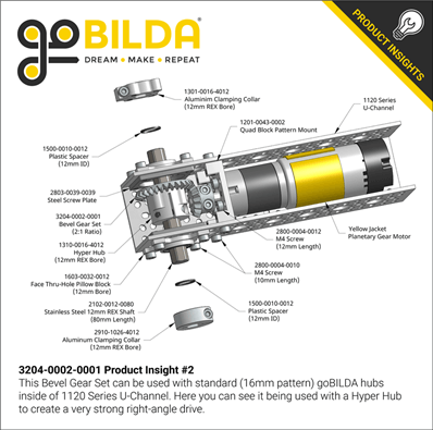
Our robot chassis and drivetrain designs were derived from existing designs in the industrial world, including cars and tanks. The original design of the chassis was a four-wheel direct-drive layout (Figure 1) with large, compliant wheels (Figure 2). The robot was intended to operate like a robust car with considerable maneuverability. The chassis would be made from aluminum U-channels and motors manufactured by GoBilda (a parts vendor for small-scale robots). The GoBilda system was purposefully made to allow various parts, like motors, to fit inside the U-channels (Figure 3). The direct drive would allow no power loss from the motors, and the four-wheel drive would allow zero-degree turning.
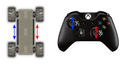
Figure 1: Sample “tank-drive” layout
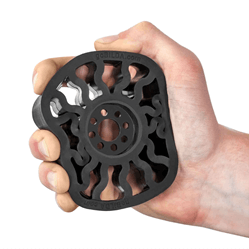
Figure 2: Compliant wheel
Upon further discussion, two factors from our original design were changed. After analyzing the UAV’s landing gear dimensions, where our payload would be attached, we found that the chassis would be too wide if we used four motors. In addition, the robot’s weight would be too heavy to allow for our drop cage and release mechanism. Our first modification was to change to a two-wheel drive system with two dead wheels and add a 2:1 bevel gear to each motor (Figure 4). We used Autodesk Fusion 360, a 3D modeling software, for all our design work. This modification doubled our torque while halving our overall speed. Additionally, it significantly decreased the overall weight and width of the chassis. After determining that the motors would fit inside the aluminum channels at a 90-degree angle, we examined the overall layout of the electronics on our robot.
Battery, wheel size, and the placement of these parts dictated the final chassis design. Compliant wheels were replaced with large GoBilda wheels designed specifically for rugged terrain. The GoBilda system was modular and scalable, so we used it for our chassis frame, motors, wheels, and electronics. The battery was placed in the centre of the long channels, keeping its mass centrally focused on our robot (Figure 4). Placing the electronics inside the U-channels allowed the robot to drive upside-down if overturned (Figure 4).
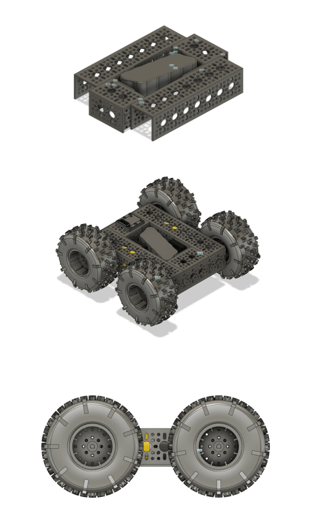
The final design of our chassis incorporated these changes. The inner width was as narrow as the battery, and the length was as short as possible, considering the combined length of one motor and one axle. The centre U-channels were 3D printed to reduce weight. The long channels that housed the motors and axles were kept aluminum to maintain rigidity. The final measurements of the chassis were approximately 290 mm wide, 305 mm long, and 135 mm tall, as compact as we could make it. The culminating chassis design can be seen in Figure 4.
When the robot package was dropped, the 3D-printed inner U-channels suffered fractures at their connection points, detaching them from the outer U-channels. However, there was no damage to the electronic components, and all non-3D-printed parts remained intact and connected. The aluminum plate on top of the robot protected the electronics (Figure 5). The robot survived the drop and was mobile. However, the aluminum plate caused the outer U-channels to bow outward, hindering the robot’s ability to navigate effectively. A new chassis redesign would opt for aluminum inner U-channels identical to the outer ones. All other aspects of the robot performed as intended and did not require alteration.
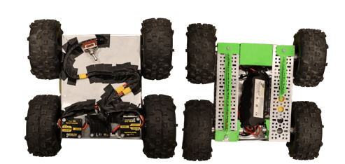 Figure 5: Top and bottom view of the robot post-drop
Drop Cage
The drop cage evolved extensively over the course of the project. Initially, a fully enclosed cage made of aluminum brackets was used to test different impact scenarios (Figure 6). Once on the ground, a door release mechanism would be needed to “open” one side of the cage for the robot to exit (Figure 6).
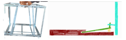
Figure 6: Initial testing drop cage and pressure plate door release mechanism
This initial drop cage was too heavy. The robot itself weighed over 6.8 pounds, and the cage weighed 4.4. Thus, the 10-pound payload limit was exceeded, and a new, lighter cage design was necessary. Since the robot could fall in any direction during the drop, we designed a T-channel and an interlocking T-beam to secure all directions of robot movement inside the cage. The T-beams connected to the robot’s underside slid into the T-channels attached to the cage platform, stopping motion in four directions. When not in motion, the robot’s motor resistance would prevent it from moving in the final two horizontal directions (Figure 7).
With the robot secured in all directions, the cage design changed from a full enclosure to an open box frame. This new rectangular frame was open on three of the six sides, significantly reducing mass. Only one surface colliding with the ground required energy absorption for protection during impact. Crumple zones or shock absorbers protect the contact surface. Another consideration for this open design required the contact surface to be consistent during every drop. Four trapezoidal guide fins were designed to guide the direction of the drop (Figure 7).
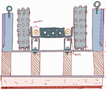
Figure 7: Draft drawing of beams, channels, and three-sided open box
When the cage design was finalized, 3D CAD models were drafted (Figure 8). The T-beam was designed to screw into the base of the robot (Figure 9), with its limiting dimension as the height difference between the robot’s bottom and the base of our drop cage. The T-channel was designed to fit the T-beam, and its limiting dimension was like the height difference between the ground and the robot’s bottom (Figure 9). Initially, the T-channel was printed as part of the cage’s base. However, for ease of replacing parts, they were printed separately. The size limitations of available 3D printers excluded printing the cage as one piece and were instead printed as left and right halves (Figure 10). A tongue-and-groove connection was designed to connect these halves, along with a plate to be secured underneath for increased rigidity (Figure 10). Additionally, a slot was designed to house the guide fin bracket (Figure 10).
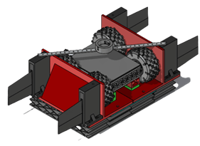
Figure 8: Final cage design with T-channels, guide fins, fin brackets, crumple zones, and magnet mount
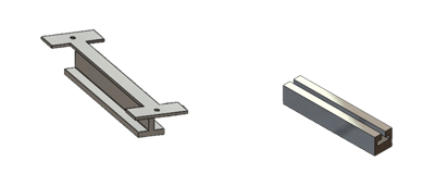
Figure 9: T-beam with holes to fasten to the robot’s underside, T-Channel that attaches to the left and right bases of the cage.
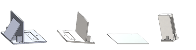
Figure 10: Left and right halves of the base with tongue connection, angle support, and bracket slot, Fin bracket with a slot for guide fin and a slot for cage connection, Connector plate with fastening holes
The manufacturing process of 3D printing was considered throughout the modeling of the cage parts. Any holes that were printed in test pieces had expanded. To compensate for this discrepancy, most holes were given a tolerance of 1-2 mm and any larger parts that would enclose an object were given a 5-10 mm tolerance. Some variables, such as material strength, would vary significantly with the 3D printer used and the applied settings (infill, layer thickness, bed temperature, etc.).
The drop cage was printed in PET-G with Ultimaker’s US3 and US5. While the 3D printed material was weak, we expected the crumple zone to absorb the energy of the impact fully. Additionally, the ten-pound payload limit made it difficult to use any material of substance, considering the robot itself was over 60% of our maximum weight. 3D printing was the most accessible manufacturing process, allowing for convenient replacement parts. Although 3D printing was easily accessible, it was not quick, resulting in a cumulative time to print the cage of over 65 hours.
The 3D-printed material did not remain intact after impact. This is because the crumple zones did not properly absorb the impact as we expected. Instead, the cage absorbed and “dispersed” energy by breaking at weaker spots. Both the left and right halves of the cage base shattered along the inner wall but remained intact along the side that had the angled support (Figure 11 A-C). The T-beam and T-channel system also did not remain intact (Figure 11 D&E). The guide fin bracket and the cage connected to it also suffered damage (Figure 11 F&G).
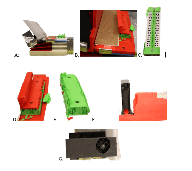
Figure 11: A. Left half of the base, shattered along the edge, B. Angled support side remaining intact, C. Right half of the base, shattered along the edge, angled support side remaining intact, D. Shattered T-beam E. Shattered T-channel F. Bracket and right half of cage shattered at slot connection, G. Shattered bracket at the connection point to the magnet mounting beam,
Additionally, due to the different printers utilized to fabricate various components, some had better strength than others. Infill percentage and pattern differed for the cage base’s left and right half (Figure 12). Predictably, because the white side was printed at a lower infill percentage, it was weaker and wholly separated from the rest of the cage. In contrast, the red side was stronger and maintained rigidity throughout the drop.
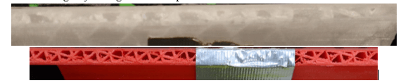
Figure 12: Cross-sectional view of the white half of cage (top) printed with a lower % infill versus the red half of cage (bottom) printed with a higher compared % infill.
While the materials used in the drop cage could have been better, the design performed as predicted. During ascent and descent, the robot remained secure inside the drop cage. After impact, the robot was able to maneuver out of the cage. While this version of the drop cage requires additional research into 3D printed material properties and other manufacturing processes, the actual design was performed successfully. It can be used as a stepping stone for future drop cage designs.
Crumple Zone
The original concept of using crumple zones came from the automotive industry. Specific sections of vehicles are designed to deform and crumple when a certain amount of force is applied to them. The amount of force needed to deform these sections was less than the amount of force a car would be subject to in a severe collision. In some use cases, designing a vehicle to crumple is more viable than creating a vehicle to withstand a large collision force.
Two pivotal factors play a role in diminishing impact force on objects. The initial factor pertains to the time required for colliding items to halt entirely, while the second involves the nature of energy conversion resulting from the force. Crumple zones optimize the interval between impact and complete stop, distributing the overall force across that period. Furthermore, the crumple zone is engineered to yield upon impact, consequently distributing energy away
from its contents (such as car passengers) rather than allowing the contents to absorb the energy. These dual outcomes safeguard enclosed contents from excessive forces and potential damage.
We decided to create a cage that implemented crumple zones to help divert and disperse the force of impact before reaching our robot, protecting it from as much damage as possible. While creating our crumple zones, we tested different designs and materials through several iterations. We began with three main designs: one inspired by a honeycomb structure (Figure 13), one based on arches (Figure 14), and finally a simple lattice design (Figure 15). Each design was 3D printed out of break-away material. We tested their flexibility by compressing with our hands, allowing us to closely observe how much the crumple zones would flex before giving in to the pressure, giving us an intuitive understanding of the force required to break them. After this rudimentary testing, we fastened the crumple zones to the bottom of a test cage and recorded the results of a 35-foot drop test. Based on performance in both testing phases, we settled on our final design of the lattice shape for its ability to absorb energy most effectively from an impact.

Figure 13: First proposed design. The left and right columns of support limited compression distance,

Figure 14: Second proposed design: Compression distance was similarly limited by the left and right columns of support,
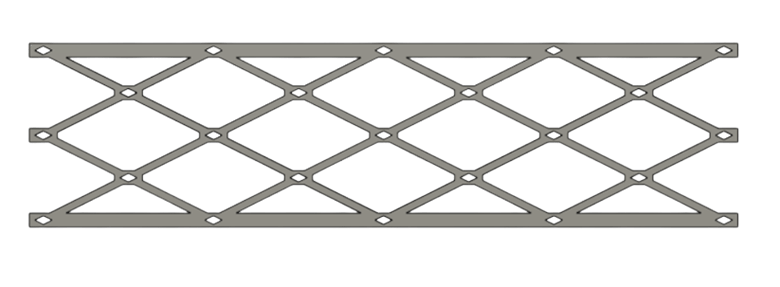
Figure 15: Final crumple zone to be attached to the drop cage. This design broke at all intersections when subjected to the equivalent force.
After testing PETG, PET, and thermoplastic polyurethane (TPU), we decided to use TPU. While TPU takes a relatively long time to print, we would only have to print it once because its durable nature allows for reuse. By changing the material of our crumple zones to a soft and flexible material, we encountered a new issue: upon impact, TPU bounces instead of statically failing. We placed a one-inch layer of soft foam underneath the crumple zones to counter this. This would also help spread out the initial impact force and ensure our crumple zone hit the ground with a larger contact area, enabling the pressure to be distributed more evenly.
On the day of the drop, the printed crumple zones worked as intended, compressing upon impact and effectively dispersing the absorbed energy. However, due to their flexibility, the amount of energy dissipated was lower than we had anticipated. This caused more energy to travel into the cage and robot. This excess energy then resulted in the shattering of several 3D-printed parts within our cage. In the future, it would be beneficial to look further into our original PETG material. As mentioned before, PETG is more rigid than TPU, so we hypothesize that it would shatter upon impact and more closely replicate the crumple zones found in cars, thus reducing the amount of energy the robot experiences.
Fins
Our initial testing phase involved dropping a rectangular payload from a four-story building. We recorded the drops using slow-motion footage and captured before-and-after images to assess the impact on our payload. Throughout this testing, we observed that the cage landed unpredictably, sometimes on its corners and other times on entirely different sides. This unpredictability posed a challenge in devising a method to absorb the kinetic energy at the point of impact, as we could not anticipate how or where the energy would disperse across the cage. Consequently, it became evident that we needed a solution to predict and control how our payload would land, leading us to explore guide fins as an apparent choice.
The United States Army has a long-standing history of incorporating guide fins to deliver explosive payloads precisely. Dating back to World War I, pilots manually released bombs from their planes and strategically guided them to their targets using fins. Motivated by this historical context, we researched the physics and aerospace engineering principles that underlie the various traits of fins. Our investigation primarily focused on academic research papers about rocket fins, providing the foundation for our design. Our inaugural design (Figure 17) adopted the clipped delta shape, like the wing structure of many passenger planes, such as the Boeing 747. Both the root chord and the tip chord feature a straightforward squared-off configuration. This design choice promotes a streamlined flow of air through the fin from the leading edge to the trailing edge, effectively mitigating any tendencies of air to flow tangentially around the fin. In contrast, the leading edge showcases a rounded profile. This facilitated the redirection of airflow, which then enveloped the fin’s surface. However, the trailing edge is beveled like a knife edge, ensuring the gradual reintegration of air to its original spatial position before it encounters the fin.
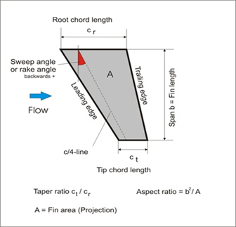
Figure 16: The various aspects of a rocket fin labeled
After further research, we discovered that the clipped delta shape is less effective at subsonic speeds. Consequently, we modified our design, increasing the surface area by extending the root chord and span lengths. This led us to reduce the abruptness of the angle of attack on the leading edge, making it far less aggressive. This adaptation resulted in a trapezoidal fin shape (Figure 17). This update to the design considerably improved our payload’s stabilization during its descent.
On the day of the drop test, our fins performed precisely as intended, strategically guiding our payload to a leveled ground impact. This ensured the even dispersion of energy across the intended contact surface. The trapezoidal shape allowed more air to contact the fin at any given moment, multiplying the force the air had and leveraging the fin’s effect on our robot’s stability. To further advance this technology, we could explore constructing the fins from a more durable yet lightweight material, such as carbon fiber. While the fins successfully fulfilled their purpose, a couple of them experienced fragmentation upon impact, showing the need for enhanced durability.
Drop Mechanism
The mounting and release mechanism for our UGV was a small yet crucial part of the overall design. It needed to be securely attached to the UAV and endure the mechanical and dynamic stresses of a 10-pound payload during flight. We devised two different designs for a release mechanism. The first design utilized a pin-and-slot system controlled by a linear actuator. When a linear servo was compared with a solenoid, the servo was ultimately selected. This choice not only decreased the required wiring but also minimized the horizontal movement of the payload. Additionally, the servo chosen was readily available for purchase from GoBilda’s inventory. A 3D model of a mock pin (Figure 18) was designed, allowing us to compare this concept with any future alternative designs. If the linear servo were to be used, concerns arose about shearing off the shaft or having the servo stall given the weight it would need to hold. Moreover, we were uncertain if our payload would be dropped perpendicular to the ground or in some other manner, rendering the use of a linear actuator as a drop mechanism even more uncanny.
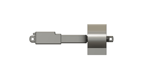
Figure 18: Early servo design
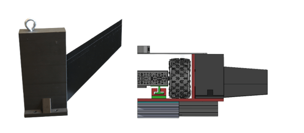
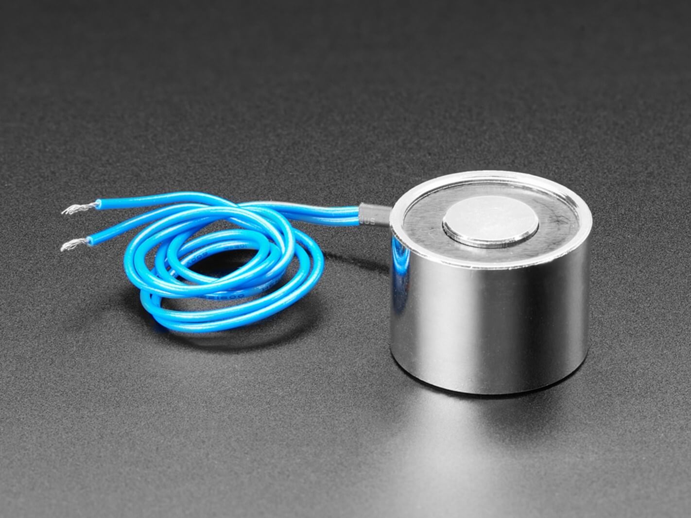
Our second design emerged after thorough consideration of magnets as a potential alternative. We adopted a reliable electromagnet solution after an in-depth exploration of magnetic options. The original design parameters mandated the ability to support a 10-pound load and adhere to the 5V terminals of the UAV’s peripherals. Through diligent research, we identified Adafruit as the sole supplier offering an electromagnet that precisely aligned with our specifications (Figure 19).
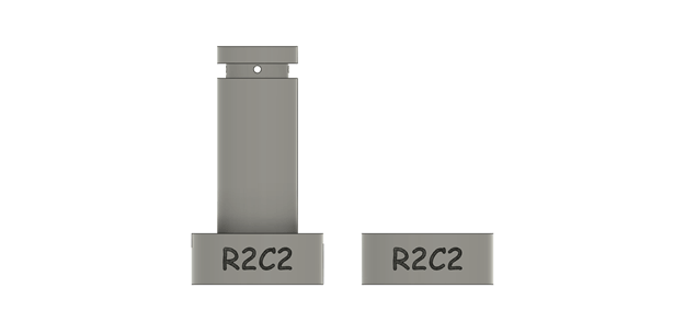
The initial UAV mount, fabricated through 3D printing, incorporated screw terminals designed to accommodate the UAV’s mounting screws. This ensured a secure attachment of the mount. The electromagnet would fit into a small cylindrical cutout on the mount and be secured by a bolt from the rear. Throughout our testing, three modifications were made to our initial design. Firstly, the diameter of the electromagnet’s housing cutout was widened to allow for a more relaxed fit. This resolved the challenges we experienced when inserting and removing the magnet from its cutout. Second, a hole placed in the wall of the mount was converted into a slot to accommodate the wiring of the electromagnet more easily. Most importantly, the length of the mount’s shaft (Figure 20) was increased to negate interference the UAV’s magnetometer was experiencing due to the magnetic field generated by the powerful electromagnet.
The mounting mechanism affixed to the UGV cage employed a design like that used for the UAV, albeit with the stem removed. This mount accommodated an additional unmagnetized electromagnet, increasing the payload capacity of our release mechanism. The activation of the electromagnet was regulated through a straightforward remote-operated relay that proved highly effective.
Conclusions
Our successful drop test demonstrated our capability to release the payload from the UAV, undergo freefall, and maintain a functional robot upon impact. We presented our research achievements, including a 3D-printed crumple zone that effectively absorbed most of the energy and aerodynamic fins that governed the cage’s descent. Additionally, we displayed our drop mechanism, which addressed crucial factors related to the compatibility of magnets and the UGV’s electronics. However, the durability of our cage had its trade-offs. Any energy not absorbed through the crumple zone’s compression was dispersed across the cage’s base, breaking some parts. Note that the cage was 3D printed using different filaments and several printers. Nonetheless, it operated according to its design, ensuring a controlled descent and enabling the robot to separate itself from the cage freely. Yet, as is typical in research, we have identified areas for improvement to enhance both the robot and cage’s survivability.
If we had the opportunity to do this project again with the same constraints, we would reinforce our robot to withstand a greater force and construct the base of our cage to be more robust. The initial focus would be on enhancing the consistency of our 3D prints. This would involve refining our selection of filament types and printer models for a more streamlined approach. Improving the consistency of our prints would increase the overall rigidity of all our 3D-printed components. Additionally, we would introduce a 3D-printed plate spanning the cage base above the crumple zone to increase its strength. Lastly, we would explore potential new designs that exclude using a cage entirely and instead focus on making our robot more robust with an integrated crumple zone undercarriage. These improvements would ultimately allow us to design a cage and robot that will survive multiple drops or have less catastrophic destruction on the cage and robot. These enhancements would yield a more resilient cage and robot capable of enduring multiple drops with reduced catastrophic damage.
Acknowledgment
We want to thank our mentors, Ms Virginia To, Mr Jeffrey Westrich, Dr Sean Gart, Mr Jason Pusey, and Mr Raymond Vonwahlde, for the technical guidance and advice that helped us stay focused and provided us with the needed resources.
Bibliography
“3613 Series Gecko® Wheel (14mm Bore, 96mm Diameter).” GoBILDA. Accessed August 25, 2023. https://www.gobilda.com/3613-series-gecko-wheel-14mm-bore-96mm-diameter/.
“5202 Series Yellow Jacket Planetary Gear Motor (13.7:1 Ratio, 24mm Length 6mm D-Shaft, 435 RPM, ⌀36mm Gearbox, 3.3 – 5V Encoder).” GoBILDA. Accessed August 25, 2023. https://www.gobilda.com/5202-Series-Yellow-Jacket-Planetary-Gear-Motor-13-7-1-Ratio-24mm-Length-6mm-d-Shaft-435-Rpm-36mm-Gearbox-3-3-5v-Encoder/.
Allen Bunkley, Justyn, Marc J Louise O. Caballes, Margaret Ajuwon, and Guangming Chen. “Design Analysis of Rocket Tail Fins Aimed at Higher Apogee by Computer Simulation.” 2022 Spring ASEE Middle Atlantic Section Conference, April 2022.
“Applications of Impulse-Momentum Change Theorem.” The Physics Classroom. Accessed August 25, 2023. https://www.physicsclassroom.com/class/momentum/Lesson-1/Real-World-Applications.
Benson, Tom. “Rocket Stability.” NASA Glenn Research Center. Last modified May 13, 2021. https://www.grc.nasa.gov/www/k-12/rocket/rktstab.html.
“Chicle | Definition, Description, & History.” Encyclopedia Britannica. Last modified July 20, 1998. https://www.britannica.com/topic/chicle.
“Crumple Zone Physics – How Plastics in Cars Can Save Lives.” Automotive Plastics. Last modified August 29, 2019. https://www.automotiveplastics.com/blog/physics-in-the-crumple-zone-demonstrate-how-less-stiff-materials-like-plastic-can-help-prevent-injury-and-save-lives/.
“Dstfuy Mini Wireless Switch 12V,5V/12V/48V/10A Relay Remote Switch for Lights,328FT Long Range for Ceiling Lights, Lamps, Industrial Control and Security Fields.: Amazon.com: Tools & Home Improvement.” Amazon.com. Spend Less. Smile More. Accessed August 25, 2023. https://www.amazon.com/dstfuy-Wireless-Ceiling-Industrial-Security/dp/B093WM5SQL/ref=sr_1_4?crid=1LW9A65AR4L6W&keywords=5v%2Bremote%2Bcontrol%2Bswitch&qid=1689776896&s=industrial&sprefix=5v%2Bremote%2Bcontrol%2Bswitch%2Cindustrial%2C77&sr=1-4&th=1.
Grabianowski, Ed. “How Crumple Zones Work.” HowStuffWorks. Last modified April 9, 2021. https://auto.howstuffworks.com/car-driving-safety/safety-regulatory-devices/crumple-zone.htm.
Hisham Shahir bin Noor Azman, Mohammad. 2022. “A Study On Aerodynamic Shape of Fin of Model Rocket Using Computational Fluid Dynamics (CFD)”. Research Progress in Mechanical and Manufacturing Engineering 2 (2):988-96. https://publisher.uthm.edu.my/periodicals/index.php/rpmme/article/view/4866.
“How to Calculate the Magnetic Force of a Solenoid.” Sciencing. Accessed August 25, 2023. https://sciencing.com/calculate-magnetic-force-solenoid-6310220.html.
Industries, Adafruit. “5V Electromagnet – 25 Kg Holding Force.” Adafruit Industries, Unique & Fun DIY Electronics and Kits. Accessed August 25, 2023. https://www.adafruit.com/product/3875.
Milligan, Tim. “What is the Best Fin Shape?” Accessed August 25, 2023. https://ftp.demec.ufpr.br/foguete/bibliografia/Apogee%2016%20What%20is%20the%20best%20fin%20shape.htm.
Nakka, Richard. “Richard Nakka’s Experimental Rocketry Site.” Richard Nakka’s Experimental Rocketry Site. Accessed August 25, 2023. https://www.nakka-rocketry.net/fins.html.
“Sizing Fins.” Space Technologies and Rocketry – STAR Public. Accessed September 14, 2023. https://rocketry.gitbook.io/public/tutorials/airframe/sizing-fins.
“Tank Drive – Robotics Simplified.” Site Not Found · GitHub Pages. Accessed August 25, 2023. https://xiaoxiae.github.io/Robotics-Simplified-Website/drivetrain-control/tank-drive/.
“Tank Drive.” Welcome! – BLRS Wiki. Accessed August 25, 2023. https://wiki.purduesigbots.com/hardware/vex-drivetrains/tank-drive.
Author Biographies
Emma Chaney is a rising sophomore at the University of Maryland Baltimore County, majoring in Bioinformatics and Computer Science. She teaches robotics and computer science to K-12 students with the Army Educational Outreach Program. After her expected graduation in 2026, Emma aspires to work in research with the government and continue her education up to her Ph.D.
Jonas Hairston is a rising Freshman at York College of Pennsylvania, majoring in Mechanical Engineering. He participated in the FIRST Tech Challenge for seven years as a primary mechanic. Jonas completed the Project Lead The Way (PLTW) engineering pathway in high school, where he improved and applied his engineering skills to solve real-world problems.
Selena Hamilton is a Junior studying Computer Science at Towson University. Having received her associate’s degree from Harford Community College, she continues to pursue higher education in pursuit of a career in Software Development. She is currently an intern with the Energetics Technology Center.
Jeremy Johnson is a Senior majoring in Computer Engineering at Virginia State University. Since Jeremy has been in college, he has held important and impactful roles in the university’s annual NASA Lunabotics project. He plans on continuing his second year as the team lead for the project as he has acquired fundamental world skills in various disciplines, such as mechanical and electrical engineering. He plans to graduate in May 2024, enter the workforce, and potentially continue his education.
Irene Macri is a senior attending Lehigh University in Bethlehem, PA, for Mechanical Engineering and is committed to Army ROTC through the Steel Battalion. At Lehigh University, she has researched Wire Arc Additive Manufacturing processes with a focus on troubleshooting, co-founded the Women’s Wrestling Club, and competed in wrestling. After her anticipated graduation in 2024, she will be commissioned into the Active Duty Army as a Second Lieutenant to pursue service and leadership.
Donovan Ramos is a sophomore majoring in computer engineering at the University of Delaware. Before entering college, he participated in the FIRST Tech Challenge for five years as a lead designer and mechanic, with one year as team captain. He is currently an intern with the Energetics Technology Center. He plans to graduate in 2026, enter the workforce as an army contractor, and eventually continue his education.
Aneesh Singh is a rising sophomore at the University of Maryland College Park, majoring in neuroscience (pre-med track) and minoring in data science. He has worked with the Army Educational Outreach Program, teaching computer science and robotics to middle and high school students. He aspires to earn a PhD in behavioral and cognitive neuroscience or attend medical school to become a pediatrician.
Maxwell Yass is a driven Senior majoring in Computer Science at the University of Wisconsin La Crosse. Dedicated to academic excellence and service, Max thrives as an active member of Army ROTC and proudly serves in the Wisconsin Army National Guard. With an anticipated undergraduate degree completion in 2024, Max’s commitment to education continues as he envisions pursuing a master’s degree. Fueled by a passion for leadership and a desire to make a meaningful impact, Max aspires to create a career within the Government sector.